
Robot gripper jaws are small parts, but they directly affect pick-and-place stability. If the gripping faces are not parallel, the part may touch on one side first, the force distribution becomes uneven and repeat placement error grows. Outer dimensions alone cannot prove the jaws will work.
A good machining plan controls gripping face parallelism, paired jaw height difference, locating hole position, mounting face flatness, anti-slip texture and surface treatment together. The inspection report should follow the same datum system as the final end effector.
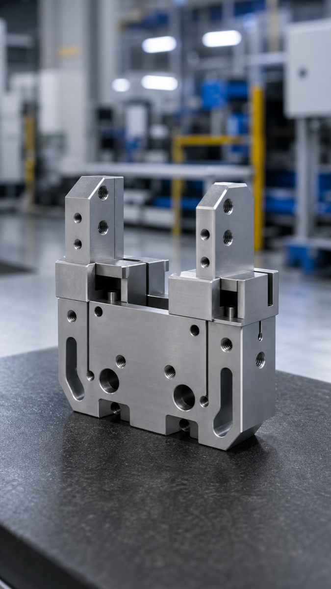
What Gripping Face Parallelism Affects
| Feature | Function impact | Possible problem |
|---|---|---|
| Gripping face parallelism | Keeps both contact faces aligned | One side contacts first and force becomes uneven |
| Paired jaw height | Controls centerline after assembly | Pick position shifts during repeated cycles |
| Locating hole spacing | Links jaw to cylinder, slide or adapter plate | Assembly becomes tight or repeat location drifts |
| Surface roughness | Balances friction and scratch risk | Workpiece slips or gets marked |
| Anti-slip texture | Controls local contact force | Left and right jaws grip differently |
| Edge break | Protects parts and operators | Sharp burrs scratch the workpiece or affect contact |
Why Gripper Jaws Drift or Grip Unevenly
Many gripper issues are not single-part failures. A jaw can pass size inspection but still fail after assembly because the left and right jaws were not measured as a pair. Thin arms, pockets, slots, serrations and repeated setups can also change the relationship between the mounting holes and gripping face.
Surface treatment adds another variable. Anodizing, hard anodizing or blasting may slightly change edge feel, roughness and local dimensions. Critical gripping faces and locating holes should be defined before surface treatment so the supplier can plan allowance and final inspection.
| Risk | Cause | Effect |
|---|---|---|
| Multiple setups | Irregular jaws require several machining directions | Datums shift between gripping face and holes |
| Long thin arms | Low stiffness during cutting | Small taper appears on the gripping face |
| Serration machining | Tool wear or uneven depth | Friction differs between left and right jaws |
| Mirror-part mismatch | Left and right parts are inspected separately | Height and centerline errors grow after assembly |
| Surface treatment | Coating or blasting changes edges | Gripping size and roughness change |
| Over-deburring | Functional edges are hand-finished too much | Contact line or locating surface changes |
Recommended Machining Route
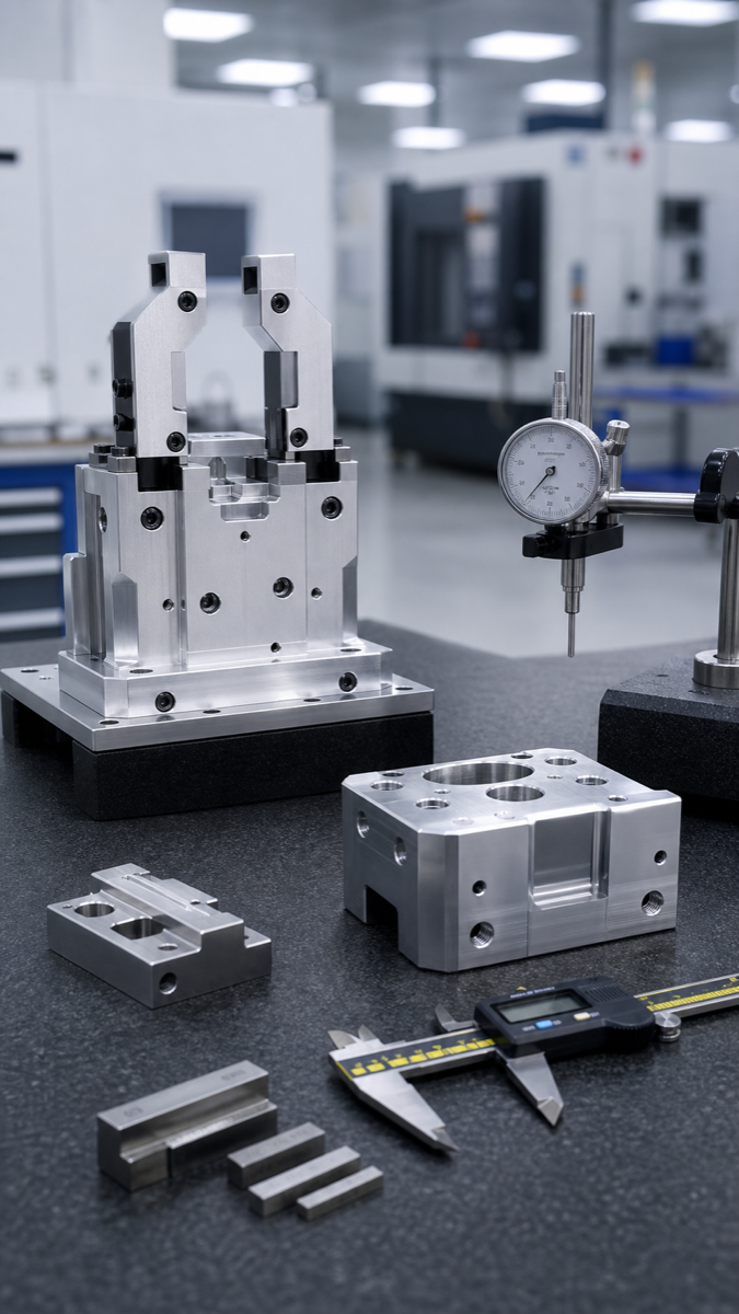
A stable gripper jaw process starts by defining the mounting datum and the true gripping faces. Roughing should remove large stock first, while functional faces keep enough allowance for final finishing. Semi-finishing then creates consistent stock on paired jaws before final gripping face machining.
Complex jaws may benefit from 4-axis or 5-axis machining to reduce setups. Thin arms or windowed lightweight structures often need soft jaws, local support blocks, low cutting force and final finishing after the part has relaxed.
| Process step | Recommended action | Control purpose |
|---|---|---|
| Rough machining | Remove large stock and leave uniform allowance | Reduce one-step distortion |
| Datum setup | Use mounting face and main locating holes | Match machining datum with assembly datum |
| Semi-finishing | Prepare paired jaws with similar stock | Improve left-right consistency |
| Final gripping faces | Use sharp tools and light finishing passes | Control parallelism and texture |
| Hole machining | Finish locating holes in the same stable setup when possible | Control spacing and position |
| Process inspection | Measure gripping faces, holes and paired relationship | Stop assembly risk before the batch |
Inspection Data Buyers Should Request
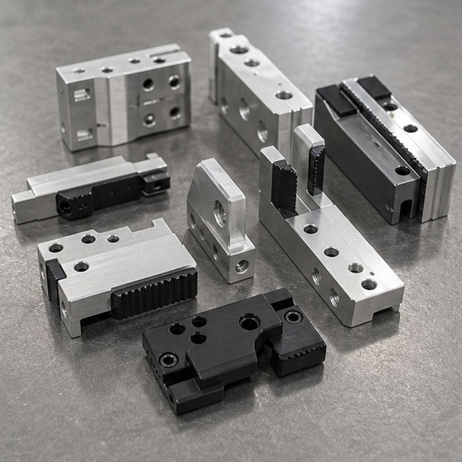
A useful inspection report should include gripping face parallelism, paired jaw height difference, locating hole position, hole spacing, mounting face flatness, thread quality, roughness and post-finish checks if surface treatment is applied. A report that lists only length, width and height is not enough for gripper acceptance.
| Inspection item | How to evaluate | Acceptance purpose |
|---|---|---|
| Gripping face parallelism | Measure relative to the mounting datum or specified reference | Confirms stable contact |
| Paired jaw symmetry | Check height and centerline after pairing | Reduces pick center shift |
| Locating hole position | CMM from datum A/B/C | Protects repeat mounting |
| Hole spacing | Gauge or CMM depending on tolerance | Prevents screw pull and tight assembly |
| Roughness or texture | Inspect gripping zone separately | Balances grip force and workpiece protection |
| After surface treatment | Spot check critical faces and holes | Confirms coating did not change function |
Material and Surface Finish Notes
Al6061 is common for prototype jaws and many lightweight gripper parts. Al7075 may be better when strength, stiffness and low weight are more important. POM or PEEK can be used when the jaw needs low friction, insulation or protection for delicate parts.
For hard-contact gripping, roughness and texture should be specified carefully. A very smooth face may slip, but an aggressive serration may mark the workpiece. The drawing should define which areas are functional gripping faces and which areas are ordinary clearance or weight-reduction features.
RFQ Checklist
| Question | Why it matters |
|---|---|
| Which faces are true gripping faces? | Keeps precision focused on functional contact |
| Should left and right jaws be inspected as a pair? | Controls assembled centerline and height difference |
| What datum defines gripping face parallelism? | Aligns inspection with assembly |
| Will serrations or texture change the final size? | Controls friction, burrs and contact consistency |
| Is post-anodizing inspection required? | Protects critical dimensions after surface treatment |
| Can first article data be tied to part numbers? | Supports traceability for low-volume iterations |
FAQ
What is often overlooked in robot gripper jaw machining?
The paired relationship between left and right jaws. A single jaw may pass size inspection, but the assembly may still have centerline or height error.
How tight should gripping face parallelism be?
It depends on workpiece size, gripping force and datum setup. The tolerance should follow the functional test and drawing requirement.
Can anti-slip texture affect precision?
Yes. Serration depth, direction, burrs and tool wear can change contact behavior, so texture zones should be defined separately from precision faces.
Do gripper jaws always need 5-axis machining?
No. Simple straight jaws may not need it. Irregular, lightweight or multi-face jaws may benefit from 4-axis or 5-axis machining to reduce setups.
What should be included in the RFQ?
Send paired part drawings, material, surface finish, gripping face notes, datum scheme, quantity and inspection requirement.
Summary
Robot gripper jaw machining is not only about milling the outer shape. The real quality target is repeatable gripping: parallel gripping faces, stable locating holes, paired-jaw consistency, controlled texture and inspection from assembly datums. Clear RFQ notes help the supplier machine only the features that truly control gripping performance.