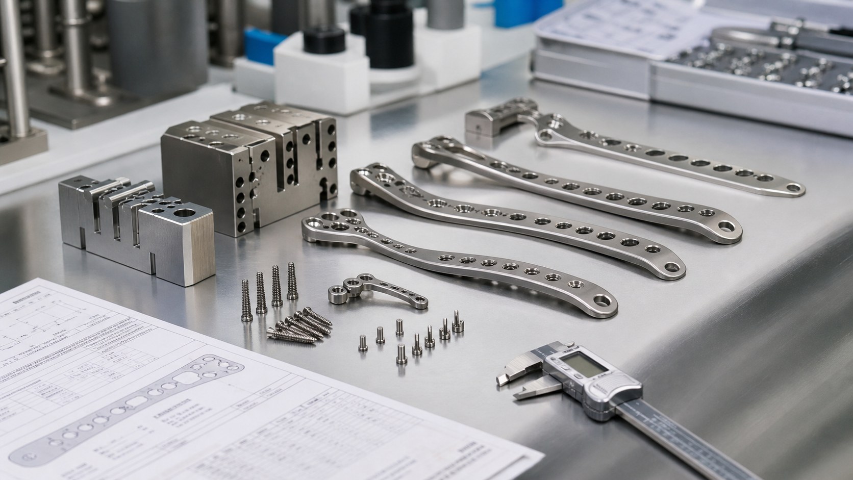
Orthopedic surgical instruments, drill guides and bone plate prototypes require more than attractive metal surfaces. Their value comes from accurate hole positions, controlled threads, stable curved geometry, safe edges and traceable inspection records. CNC machining is well suited for prototype validation and small-batch development when functional requirements are translated into clear drawings and inspection plans.
Functional geometry should lead the drawing
Bone plates, drill guides and trial instrument parts usually contain several feature types that interact with each other: locking screw holes, countersinks, guide sleeves, pin holes, slots and curved support surfaces. The drawing should identify which features control alignment and which surfaces are only clearance or cosmetic.
A practical RFQ package includes STEP data, 2D drawings, datum scheme, material grade, edge requirements and quantity. If the part mates with screws, pins or other instruments, the matching component data should be shared so the machining supplier can verify assembly fit instead of only individual dimensions.
Material selection affects machining strategy
Titanium alloys are common for orthopedic prototypes because they combine strength, corrosion resistance and low weight, but they require sharp tools, stable cutting conditions and careful heat control. Stainless steel is useful for surgical guide blocks, instrument handles and wear surfaces where rigidity and durability matter. PEEK may be selected for radiolucent fixtures or lightweight trials.
The drawing should state whether material certificates, heat treatment records, passivation, polishing or cleaning documentation are required. Even for non-implant prototypes, these notes help align machining, finishing and inspection expectations.
Locking holes and threads need controlled process steps
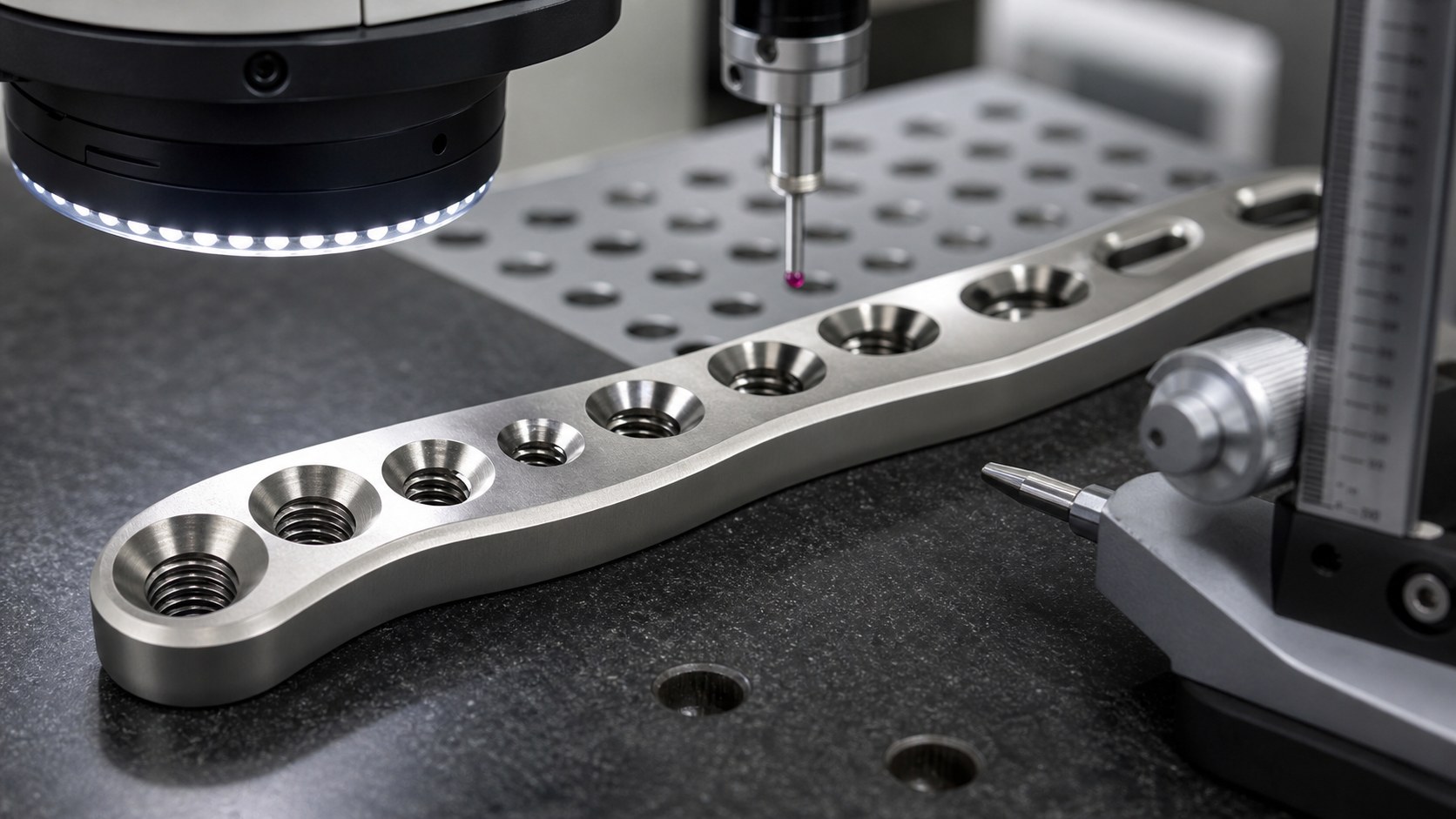
A locking screw hole is a functional system, not a simple drilled feature. Countersink angle, thread form, pitch diameter, depth, coaxiality and edge condition all influence how the screw starts and seats. CNC programs often separate rough drilling, interpolation, thread milling or tapping, fine chamfering and final deburring into controlled steps.
Inspection should include thread gauges, optical checks of countersinks, CMM location data and microscope review for edge quality. If a trial screw is available, functional fit testing can reveal issues that a dimension-only report may miss.
Curved profiles require stable fixturing
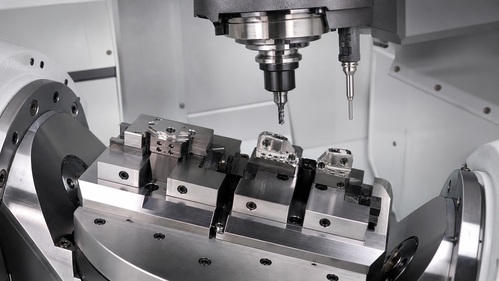
Orthopedic plates often have long curved profiles and thin bridges between holes. These shapes can vibrate, spring back or distort if clamping is not planned carefully. Custom nests, soft jaws, support pins and staged roughing can hold the part without crushing delicate areas.
For 5-axis or 3+2 machining, fixture access is just as important as clamp force. The setup must expose side windows, countersinks and edge blends while keeping datums repeatable for inspection. A small change in workholding can have a large effect on hole alignment.
Burr control is a medical-device priority
Burrs around holes, slots and threads can interfere with screw seating, trap debris or damage mating instruments. Orthopedic prototypes should define acceptable edge breaks, no-loose-burr requirements and special protection for threads, bores and polished contact areas.
Deburring may combine hand work, abrasive flow, micro tools, brushes and microscope verification. Finishing steps such as blasting or polishing should be validated so they improve edges without changing critical dimensions.
Inspection reports should match the intended use
For engineering validation, a useful report should confirm hole positions, thread gauges, countersink geometry, profile tolerance, flatness or curvature, slot width, surface finish and datum alignment. CMM data is useful, but photos of thread gauges and microscope checks often make review faster.
When the prototype will be used in assembly testing, inspection should also include fit checks with pins, trial screws or mating guide blocks. This creates evidence that the machined part supports the intended mechanical function.
Clean packaging protects traceability
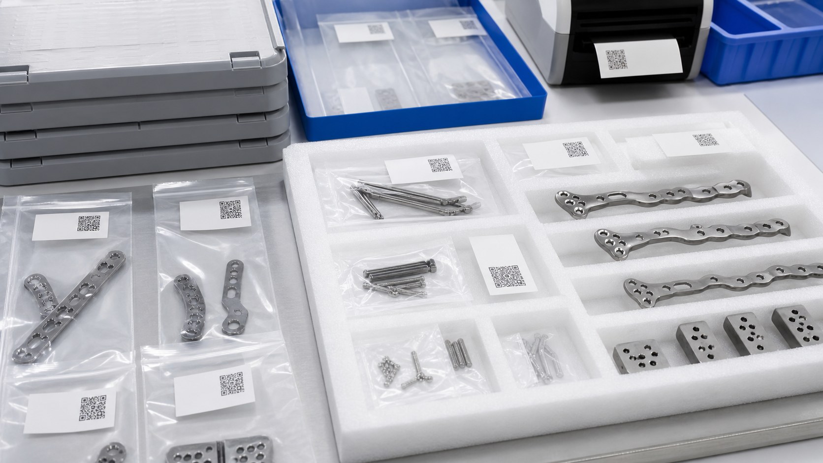
Small screws, pins, plates and guide blocks can be mixed easily after machining. Individual bags, foam trays and labels keep parts separated by revision, material, lot and inspection status.
Clean packaging is especially helpful for international prototype programs because it reduces receiving confusion and preserves the condition of polished or deburred surfaces during shipping.
FAQ: Orthopedic CNC Machining
What drawings are needed for orthopedic prototype machining?
Send STEP files, 2D drawings, material grade, hole and thread callouts, surface finish requirements, inspection datums and expected quantity. Assembly information helps define critical features.
Which materials are common for orthopedic trial parts?
Titanium alloys, stainless steels and PEEK are common choices. The best material depends on strength, corrosion resistance, weight, test purpose and documentation needs.
How are locking screw holes controlled?
Countersink angle, thread form, pitch diameter, bore location and coaxiality should be inspected with thread gauges, optical measurement, CMM checks and microscope review.
Can curved bone plate prototypes be CNC machined?
Yes. Multi-axis machining, custom nests, soft jaws and staged stress control help maintain the curved profile while protecting thin edges and hole positions.
What burr-control requirements should be specified?
Specify no loose burrs, define edge break ranges, protect threads and bores from media changes, and require microscope inspection on holes, slots and contact surfaces.
What quality documents can be supplied?
Typical documents include material certificates, dimensional reports, thread gauge records, surface finish data, CMM reports, photos of critical checks and packaging labels.
有零件加工需求请扫码,唐经理:17706216422(微信同号)