
A robot controller aluminum housing looks like a simple box, but it carries several functional requirements at the same time. It must protect electronics, align connectors, support PCB or heat-sink surfaces, seal against dust or splash and still remain light enough for robot integration.
Most quality problems do not come from the outer shape. They come from deep cavity machining, thin-wall spring-back, cover sealing face flatness, connector hole position, threaded boss accuracy and burrs around cable or plug openings. These areas should be reviewed before quoting and before choosing the fixture.
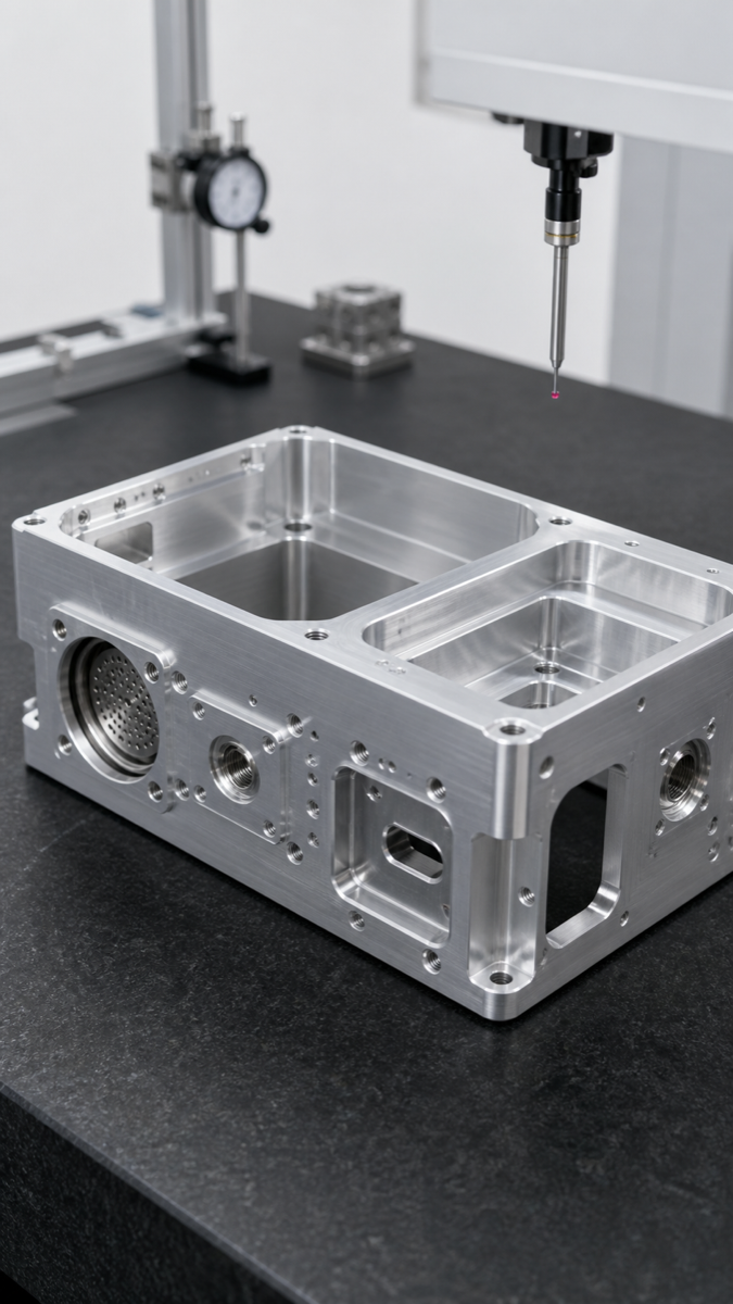
Functional Zones to Define First
| Housing zone | What it controls | Typical machining risk |
|---|---|---|
| Cover sealing face | Gasket compression and dust protection | Flatness change after deep cavity roughing |
| Connector interface holes | Plug alignment and installation force | Position drift after multiple setups |
| PCB mounting bosses | Board height and screw assembly | Thin boss vibration or thread burrs |
| Bottom mounting holes | Robot frame alignment | Datum inconsistency between bottom and side faces |
| Heat transfer surface | Contact with heat sink or thermal pad | Tool marks or flatness error |
| Cable windows | Cable routing and strain relief | Sharp edges and local deformation |
Deep Cavity and Thin Wall Risks
Deep cavity machining removes stock from the inside while the outside must stay stable. If the roughing is too aggressive, the wall can release stress and move. If the clamp is too strong, the part may look correct on the machine but open up after unclamping.
A practical process often leaves balanced stock, roughs the cavity in stages, supports the open side, semi-finishes critical datums and then finishes sealing faces and interface holes late in the process. This is slower than simply cutting the pocket in one pass, but it gives the buyer a better chance of receiving parts that assemble without rework.
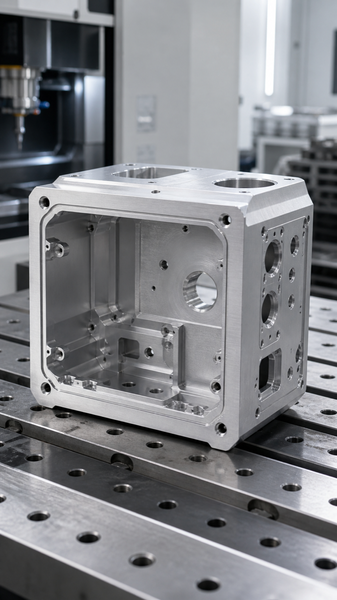
| Risk | Process control | Buyer check |
|---|---|---|
| Wall opening after release | Use soft jaws, support blocks or low-distortion clamping | Ask how free-state size is verified |
| Sealing face not flat | Leave finishing allowance and finish after roughing stress release | Define flatness and gasket area |
| Cavity chatter | Choose stable tool length and stepdown | Review surface requirement inside the cavity |
| Interface hole drift | Machine critical holes from stable datums | Define datum A/B/C on the drawing |
| Thread burrs | Use controlled chamfer and thread gauge check | State thread class and gauge requirement |
| Anodizing size shift | Define before or after finish dimensions | Mark critical holes that need masking or reaming |
Connector Holes Need More Than Diameter Control
For a controller housing, connector holes are often the most sensitive features. A connector may fit the hole diameter but still fail because the hole pattern is shifted, the counterbore is too shallow, the gasket land is not flat or the edge burr scratches the cable seal.
The drawing should identify which holes locate the connector, which holes are only for clearance and which surface is the sealing or mounting datum. When several connector openings sit on different faces, the supplier should plan the datum chain before machining starts.
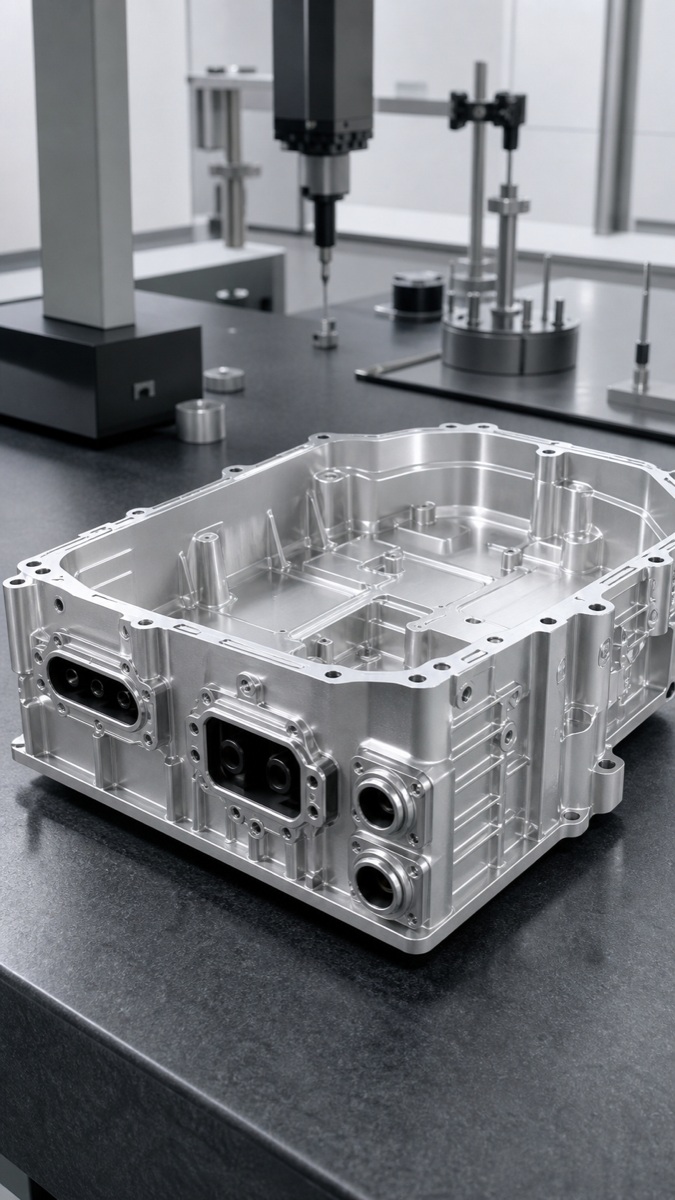
Recommended Process Route
| Step | Purpose |
|---|---|
| DFM review of datums and wall thickness | Find deformation and access risk before quoting |
| Rough outside reference surfaces | Create stable locating surfaces for later operations |
| Stage rough deep cavities | Release stress gradually and avoid sudden wall movement |
| Semi-finish bosses and sealing faces | Leave controlled allowance for final accuracy |
| Machine connector holes from fixed datums | Protect position relationship across faces |
| Finish sealing faces and critical holes | Control the final assembly features |
| Deburr and clean connector openings | Avoid gasket cuts, cable damage and assembly scratches |
| CMM and gauge inspection | Confirm hole position, flatness, threads and free-state dimensions |
Inspection Items Buyers Should Request
For small batches, a first article report is often enough if it covers the functional zones. The buyer should not request a full report for every cosmetic pocket, but critical mounting holes, connector hole patterns, sealing face flatness and thread gauges should be checked.
| Inspection item | Suggested method | Reason |
|---|---|---|
| Sealing face flatness | CMM or surface plate method | Prevents leakage or uneven gasket compression |
| Connector hole position | CMM from defined datums | Protects plug alignment |
| Mounting hole spacing | CMM or calibrated fixture | Controls robot frame assembly |
| Thread quality | Go/no-go gauge | Avoids stripped screws or blocked assembly |
| Free-state wall size | Measure after unclamping | Confirms real shape |
| Anodized critical holes | Final gauge after surface treatment | Checks coating allowance |
RFQ Checklist
| What to send | Why it helps |
|---|---|
| STEP file and 2D drawing | Combines geometry, tolerances and datums |
| Connector models or datasheets | Clarifies hole pattern and sealing area |
| PCB or heat-sink stack height | Protects internal clearance and boss height |
| Surface finish and anodizing requirement | Allows allowance planning |
| Quantity and expected repeat order | Guides fixture and inspection investment |
| Critical-to-function notes | Keeps cost focused on assembly features |
FAQ
Why do aluminum controller housings deform after machining?
Deep cavities, unbalanced stock removal and excessive clamping can release stress or bend thin walls after the part is unclamped.
How can connector hole position be controlled?
Define a clear datum system and machine critical holes from stable datums with CMM verification.
Should sealing faces be machined early or late?
They are usually finished late after roughing stress has been released, so final flatness is more stable.
Will anodizing affect connector holes?
Yes, anodizing adds a coating layer and may reduce hole size. Critical holes should be planned for final size after finishing.
What information should a buyer provide?
Send drawings, connector information, critical datums, finish requirement, quantity and inspection needs.
Summary
Robot controller aluminum housings require more than box-shaped milling. The important work is controlling deep cavity stress release, thin-wall clamping, sealing face flatness, connector hole position and final inspection. Clear functional notes allow the supplier to focus precision where it matters and keep the rest of the housing cost practical.