
PEEK is often chosen for precision parts because it has high temperature resistance, chemical resistance, wear resistance and good electrical insulation. It is used in robotics, medical devices, semiconductor equipment, aerospace fixtures and high-end automation. But PEEK is not machined like aluminum or stainless steel.
The main buyer concern is usually simple: will the part hold tolerance after machining, deburring and assembly? To answer that, the supplier must control cutting heat, clamping pressure, tool sharpness, machining sequence, edge finishing and inspection conditions together.
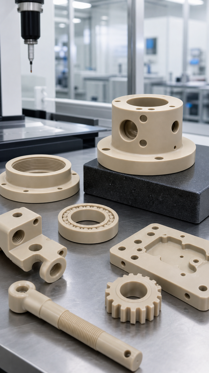
Why PEEK Parts Are Difficult to Machine
| Machining risk | Why it happens | Typical result |
|---|---|---|
| Deformation | PEEK has lower stiffness than metal and reacts to clamping load | Thin walls or long slots move after unclamping |
| Size drift | Cutting heat and elastic recovery can change the final dimension | Bores or pockets pass during machining but move later |
| Burrs | A dull tool can smear the edge instead of cutting cleanly | Hole entries, slots and threaded areas need extra work |
| Internal stress | Large material removal or aggressive roughing can release stress unevenly | Flatness and hole position become unstable |
| Surface damage | Too much heat or rubbing can polish, melt or tear the surface | Appearance and sealing contact become inconsistent |
| Inspection error | Measuring while the part is clamped hides spring-back | The buyer receives parts that fail free-state assembly |
Features That Need Early Review
Not every PEEK dimension needs a tight tolerance. The supplier should first separate functional features from visual or clearance features. Bearing bores, sliding grooves, threaded holes, sealing faces, insulating contact surfaces and datum holes deserve more process attention than non-functional pockets.
For thin-wall parts, the drawing should show which surface is the assembly datum, whether dimensions are measured before or after deburring and whether the part will be loaded during use. This context helps the machining team avoid making every surface unnecessarily tight.
| Part feature | Main control point | Useful drawing note |
|---|---|---|
| Thin walls | Reduce clamping force and leave balanced stock | Define free-state inspection |
| Small holes | Use sharp drills, pecking and burr control | State pin, screw or clearance function |
| Threaded inserts or threads | Prevent entry burrs and thread tearing | Define thread gauge and chamfer |
| Flat sealing faces | Avoid heat marks and uneven support | Call out flatness and surface requirement |
| Long slots | Rough symmetrically and finish after stress release | Identify mating part and clearance |
| Mixed thick and thin areas | Use staged machining to release stress gradually | Avoid one blanket tolerance for all features |
Process Controls That Actually Help
A stable PEEK process usually starts before the first toolpath. Material grade, sheet or rod direction, blank size and stress condition should be confirmed. If the part removes a large amount of stock, the process may need roughing, rest time and semi-finishing before final cuts.
Tooling is another key point. Sharp carbide tools, suitable rake angles and clean chip evacuation reduce rubbing. PEEK does not forgive a worn tool: burrs, surface smearing and local heat can appear quickly. Coolant or air blast should be selected according to the part function and cleanliness requirement.
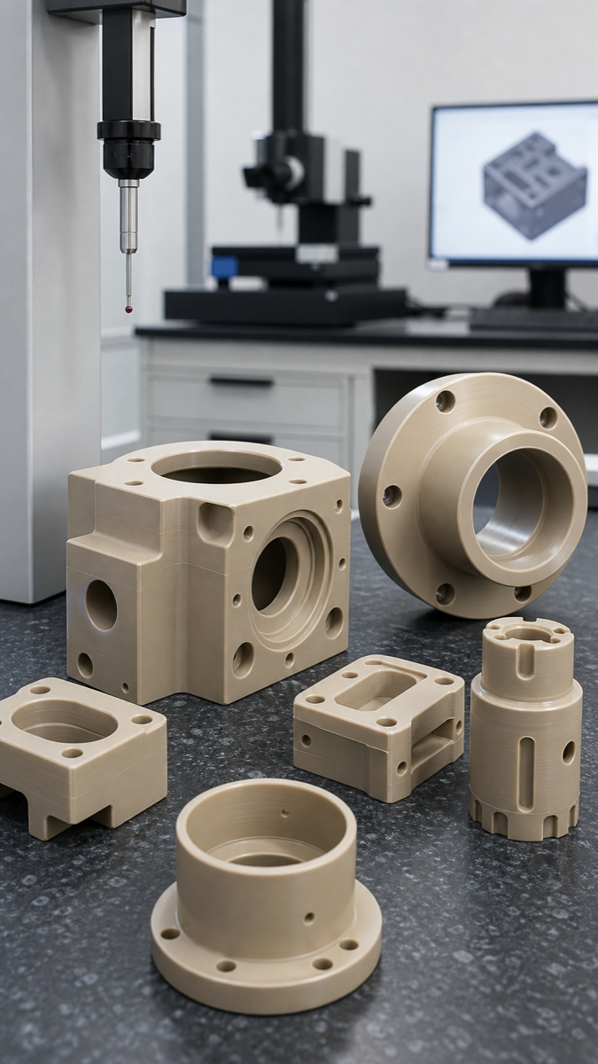
| Control action | Buyer benefit |
|---|---|
| Soft jaws or custom support | Reduces clamp marks and shape recovery |
| Balanced roughing on both sides | Controls stress release and flatness |
| Leave finishing allowance | Keeps final cuts light and predictable |
| Sharp tools and stable chip removal | Reduces heat, smearing and burrs |
| Finish datums late in the process | Keeps functional references more accurate |
| Inspect after unclamping | Shows the real assembly condition |
How to Control Burrs Without Changing Size
Deburring is not just a cosmetic step for PEEK. If edge removal is too heavy, small holes, sealing lands, guide slots and locating steps can lose size. The better approach is to prevent heavy burrs during cutting and then use controlled edge finishing.
For precision PEEK parts, the deburring method should be matched to the feature. A clearance edge can allow a larger break edge. A sealing face or locating bore may need only a minimal hand finish under magnification. The drawing should state whether sharp edges are allowed in functional areas and whether a maximum edge break is required.
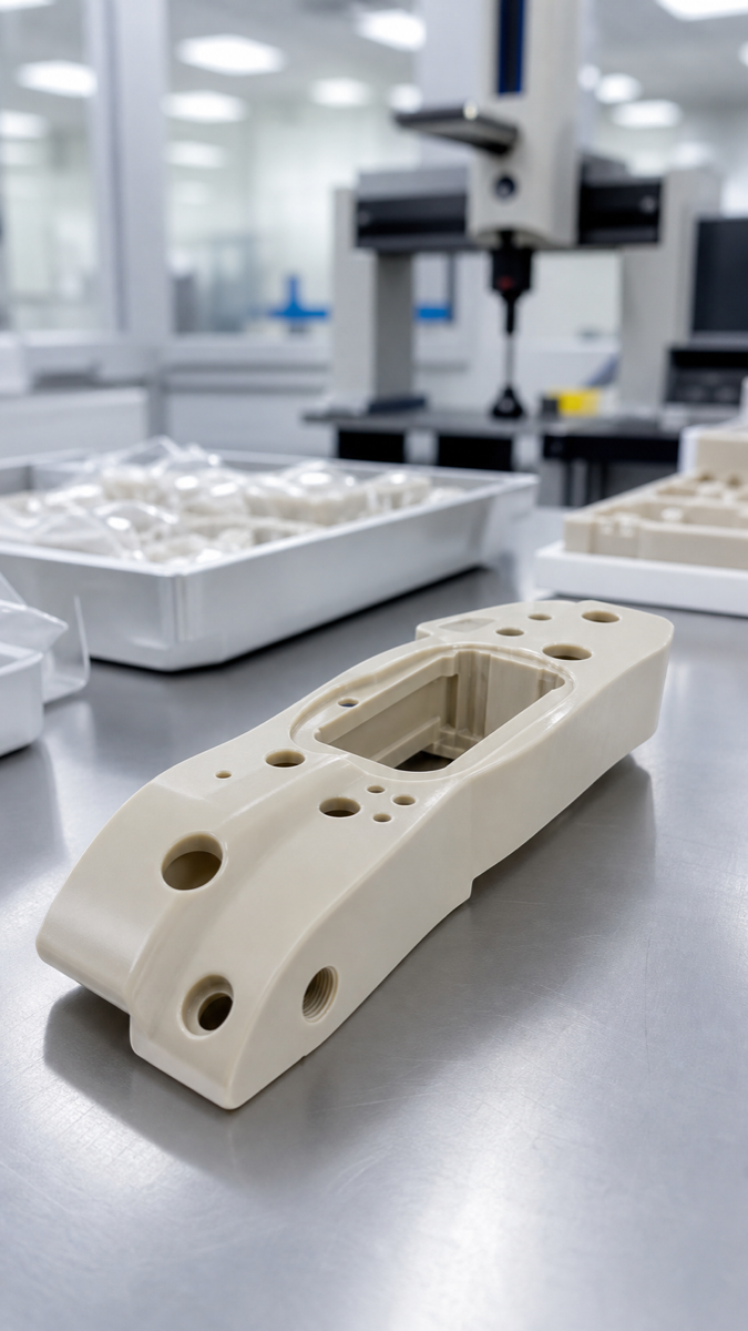
Inspection Plan for Stable Dimensions
| Inspection item | Recommended approach | Why it matters |
|---|---|---|
| Bore diameter | Plug gauge, bore gauge or CMM depending on tolerance | Confirms fit after spring-back |
| Hole position | CMM with defined datums | Protects assembly alignment |
| Flatness | Inspect in free state on a stable support | Avoids clamping distortion in the report |
| Threads | Go/no-go gauge and visual edge check | Prevents assembly damage |
| Edge break | Visual or microscope check for critical features | Avoids over-deburring |
| Batch repeatability | First article plus spot checks | Keeps small-batch production consistent |
RFQ Checklist for PEEK Parts
When sending a PEEK part RFQ, do not only send the 3D model. A useful request should include the PEEK grade, 2D drawing, tolerance focus, quantity, expected use, assembly condition, surface requirement and inspection requirement. If the part will be used in medical, semiconductor or electrical insulation equipment, cleanliness and documentation should be discussed early.
| RFQ information | What it helps the supplier decide |
|---|---|
| PEEK grade or material brand | Tooling, heat control and purchasing plan |
| Critical dimensions | Which features need tighter process control |
| Assembly function | Fit, sliding, sealing or insulation priority |
| Quantity and repeat orders | Fixture investment and inspection frequency |
| Deburring limit | How much edge break is acceptable |
| Inspection report need | Whether CMM, gauges or first article data are required |
FAQ
Can PEEK hold tight CNC tolerances?
Yes, but the process must control clamping, heat, tool wear and inspection state. Thin walls and long slots need special review.
Why do PEEK parts deform after machining?
Common causes include excessive clamping force, unbalanced material removal, cutting heat and internal stress release.
Does deburring change PEEK part size?
It can. Critical holes, sealing edges and locating steps should use controlled edge finishing with a defined maximum edge break.
Is coolant allowed when machining PEEK?
It depends on the part function and cleanliness requirement. Some parts use coolant, while others use air blast or dry machining with careful heat control.
What should buyers mark on a PEEK drawing?
Mark critical datums, fits, thread requirements, edge limits, inspection method and whether dimensions are checked in the free state.
Summary
PEEK precision machining is not difficult because the material is exotic; it is difficult because small process details change the final dimensions. A good supplier controls stock removal, clamping, tool sharpness, heat, deburring and free-state inspection as one system. For buyers, clear drawings and functional notes are the fastest way to reduce rework and receive parts that assemble correctly.