
The difference between 3-axis, 4-axis and 5-axis CNC machining is not simply that one is more advanced. For robot parts, the real question is how many faces, hole directions and critical datums can be machined with fewer setups.
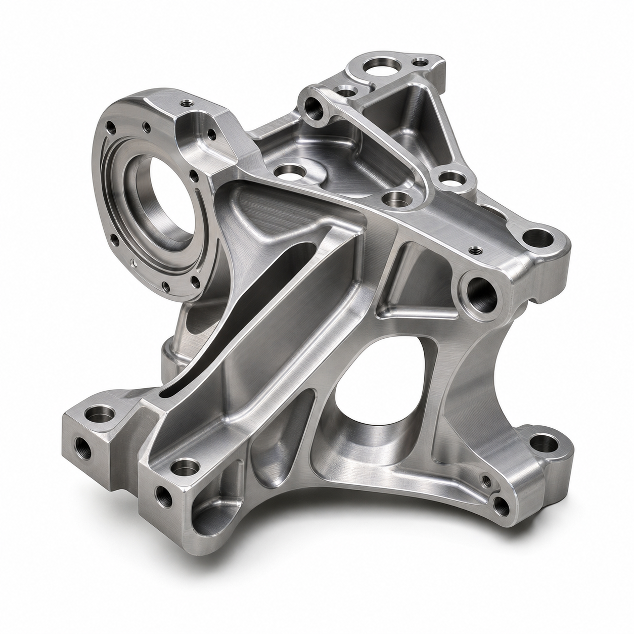
Flat plates and simple brackets may be fine on 3-axis CNC. Side holes and regular circular features may benefit from 4-axis machining. Complex lightweight brackets, angled sensor faces, deep pockets and multi-direction hole systems are often better candidates for 5-axis machining.
Core Difference
| Item | 3-axis CNC | 4-axis CNC | 5-axis CNC |
|---|---|---|---|
| Motion | X, Y and Z linear movement | Adds one rotary axis | Adds two rotary axes or indexed multi-angle machining |
| Typical parts | Flat plates, simple covers, one-side holes | Cylindrical parts, side holes, regular multi-face parts | Complex brackets, angled holes, deep pockets, multi-datum parts |
| Setup count | Multiple setups for several faces | Can reduce some re-clamping | Can reduce setup changes significantly |
| Accuracy risk | Datum shift after flipping | Rotary positioning must be controlled | Programming and fixturing are harder, but datum chain can be more stable |
| Cost logic | Lower machine cost | Medium cost | Higher programming and machine time, but less rework risk |
| Best stage | Simple prototypes | Medium-complex prototypes | Functional validation and low-volume precision parts |
When 3-Axis CNC Is Enough
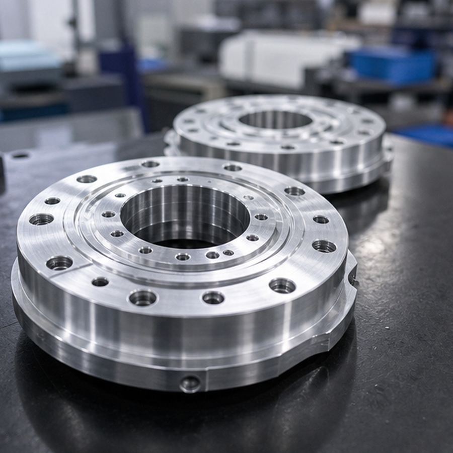
3-axis CNC is suitable when the main features are on one side or can be machined from simple datums. Robot cover plates, simple mounting blocks, flat sensor plates and cable clamps are common examples.
The risk increases when precision holes are split across top, side and angled faces. Every time the part is flipped and re-indicated, the accumulated datum error can become more important than the nominal machine accuracy.
When 4-Axis or 5-Axis Should Be Evaluated
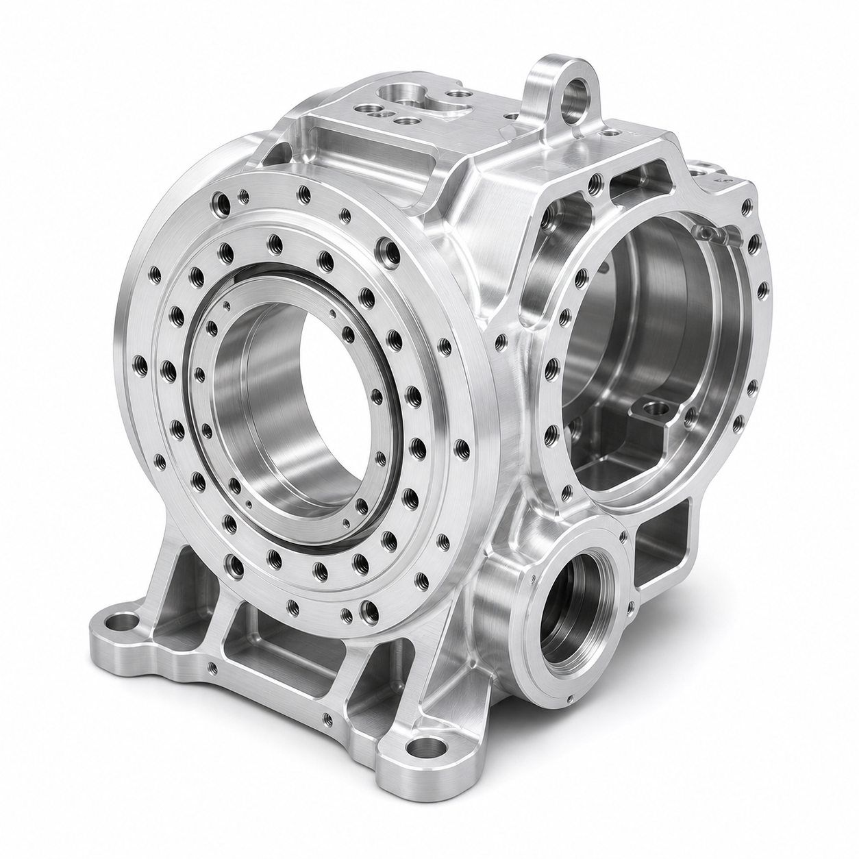
4-axis machining helps with circular patterns, side holes and features that follow a regular rotation. 5-axis machining is useful when the part has angled surfaces, organic lightweight pockets, deep access regions or multiple hole directions that need one stable coordinate system.
| Part situation | Recommended evaluation | Reason |
|---|---|---|
| Side holes on a cylindrical part | 4-axis | Reduces manual flipping and re-datuming |
| Regular multi-face holes | 4-axis or 3+2 | Balances cost and setup stability |
| Angled sensor mounting faces | 5-axis | Reduces fixture changes and tool interference |
| Lightweight robot frames | 5-axis | Improves tool access to pockets and ribs |
| Thin-wall multi-face brackets | 5-axis with staged machining | Helps manage clamping and datum drift |
| Low-volume parts with repeat accuracy | 5-axis evaluation | First-article process can be repeated for the batch |
Risks of Choosing the Wrong Axis Strategy
| Risk | Common cause | Possible result |
|---|---|---|
| Hole position error | Too many setups and inconsistent datums | Pins, bearings or sensors do not assemble smoothly |
| Coaxiality drift | Opposite features are machined separately | Robot joints may bind, heat or wear faster |
| Thin-wall deformation | Poor clamping and cutting sequence | Part springs back after release |
| Tool interference | Deep pockets or angled faces not reviewed | Toolpath changes or rework during machining |
| Finish allowance error | Anodizing or coating ignored | Holes become tight or mating faces change |
How OEMach Usually Makes the Decision
OEMach does not choose 5-axis machining only because the machine is available. The review starts from part function: which holes locate bearings, which surfaces are datums, which pockets are only weight reduction and which tolerances affect assembly.
For a multi-face robot bracket, the process may combine 5-axis machining, soft jaws, vacuum support, staged roughing and final CMM inspection. Critical holes can be controlled tightly while non-functional lightening pockets can keep a practical tolerance.
RFQ Questions for Buyers
| Question | Purpose |
|---|---|
| How many machining faces does the part have? | Checks whether 3-axis is enough |
| Do critical holes cross several directions? | Shows whether 4-axis or 5-axis should be evaluated |
| Which dimensions actually control assembly? | Avoids making every feature unnecessarily tight |
| How will thin-wall regions be clamped? | Checks deformation control |
| Can a CMM report be provided? | Confirms first article and batch acceptance |
| Will later batches reuse the same process? | Checks consistency after prototype approval |
FAQ
Do robot parts always need 5-axis CNC machining?
No. Simple plates and one-side features can use 3-axis. Multi-face holes, angled mounting faces and complex lightweight structures should be evaluated for 5-axis.
What is the main difference between 4-axis and 5-axis CNC?
4-axis usually adds one rotary axis for side holes or circular features. 5-axis can handle more angles and complex spatial relationships.
Why can 5-axis reduce robot part error?
It can reduce repeated flipping and re-datuming, so holes and datums in different directions can stay in one more stable coordinate system.
Is 3-axis CNC always cheaper?
The machine time may be lower, but repeated setups, rework or failed prototypes can make total cost higher.
Should buyers directly specify 5-axis CNC?
It is better to send drawings and usage context, then let the supplier review DFM and explain which features truly need 5-axis control.
Summary
Choosing 3-axis, 4-axis or 5-axis CNC machining depends on machining faces, hole directions, fixture strategy and geometric tolerance risk. For robot parts, the best process is the one that controls functional datums with fewer unnecessary setup changes while keeping cost practical.