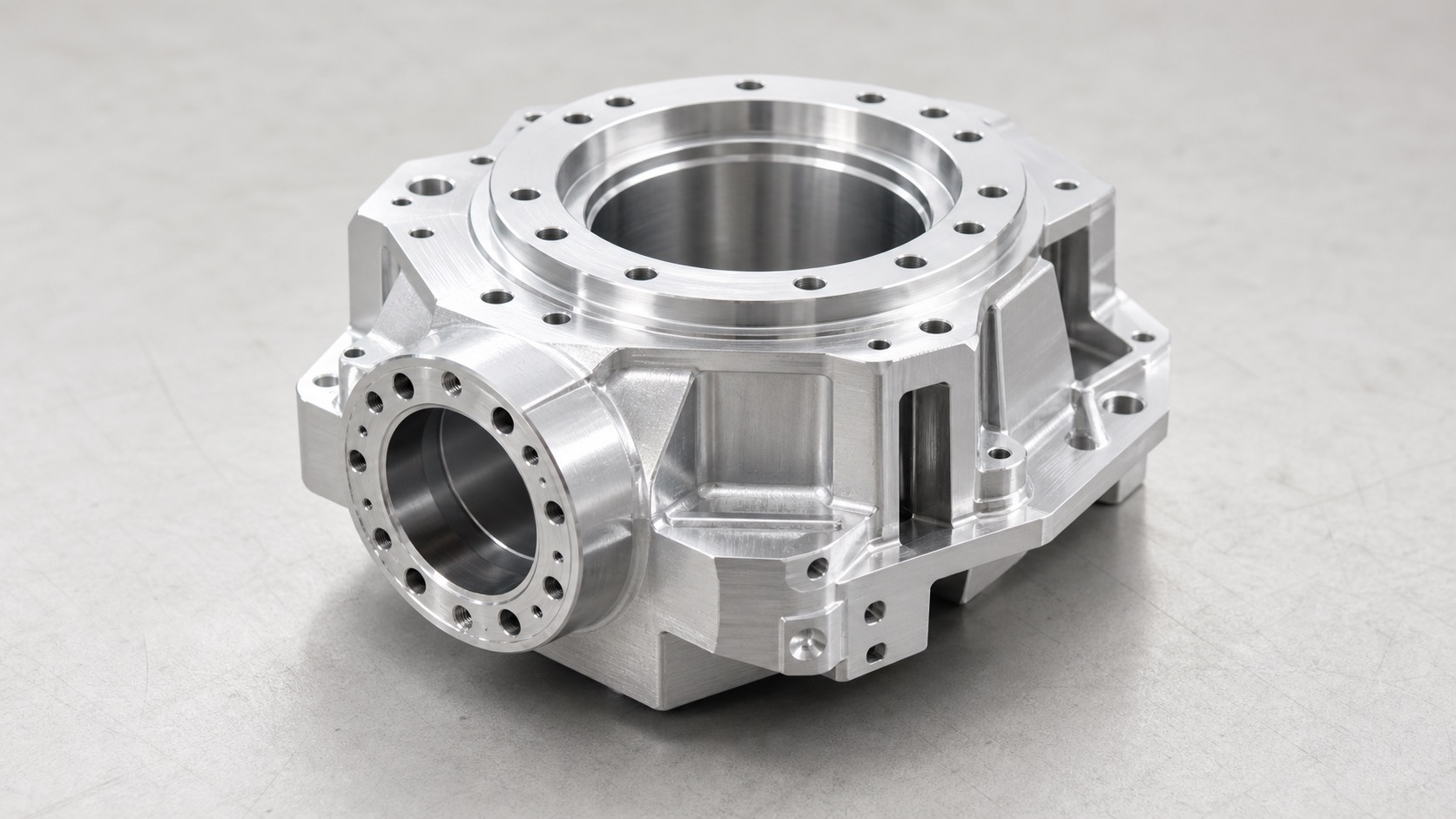
Robot joint motor housing CNC machining is mainly about controlling the relationship between bearing bores, end faces, bolt circles and locating datums. The part may look like a rigid aluminum housing, but once bearings, motor stator, encoder and gearbox components are assembled, small geometric errors can become motion noise, heat or repeatability drift.
The most important dimensions are usually not the outside profile. Buyers should focus on bearing bore coaxiality, bore roundness, end-face runout, mounting face flatness, bolt-circle position and burr control around precision holes.
A better manufacturing plan separates roughing, stress release, datum repair, precision boring and final inspection. This article explains what engineers and buyers should specify before sending an RFQ for robot joint motor housings.
Direct Answer
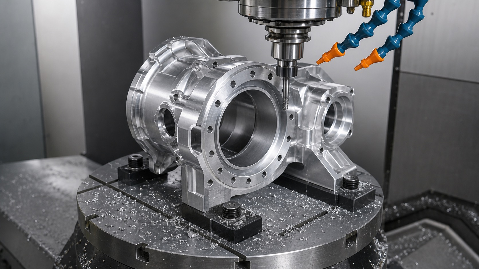
To control a robot joint motor housing, machine the bearing bores and critical end faces under one datum strategy. Do not finish one bearing bore early and then use several flipped setups to create the opposite bore and motor mounting face. That path increases coaxiality and runout risk.
For prototype and low-volume robot housings, critical bearing and end-face features may require process attention around +/-0.005 mm to +/-0.01 mm, while pockets, ribs and clearance areas can normally use practical general tolerances. The drawing should make this difference clear.
Which Features Matter Most?
The housing connects multiple precision components. If the bore axis, end face and bolt pattern are not controlled together, the assembly can force bearings and shafts into a stressed condition even when every single diameter appears acceptable.
| Feature | Why it matters | Possible assembly issue |
|---|---|---|
| Bearing bore | Defines bearing support and shaft center | Bearing preload, heat or rotation resistance |
| Opposite bore or coaxial bore | Controls motor and gearbox alignment | Shaft misalignment and noise |
| End face | Supports motor, reducer or encoder stack | Axial runout and uneven contact |
| Bolt circle | Controls clamping force distribution | Housing pulled out of alignment after tightening |
| Locating shoulders and dowel holes | Support repeat assembly | Position drift after maintenance |
| Cable and sensor windows | Protect wiring and sensor clearance | Interference or cable abrasion |
Common Machining Risks
Many robot joint housing problems are caused by process sequence, not by machine capability alone. Long cycle time, heavy stock removal, thin ribs and multiple setups can all move the functional axis.
| Risk | Typical cause | Buyer impact |
|---|---|---|
| Bore coaxiality error | Bearing bores finished in different datum setups | Motor shaft or reducer input misalignment |
| End-face runout | Face and bore finished separately | Uneven bearing or motor contact |
| Bore out-of-round | Excessive clamping force or thin-wall spring-back | Bearing fit becomes unstable |
| Bolt-circle shift | Hole pattern created after datum drift | Clamping pulls housing sideways |
| Surface-treatment size change | Anodizing or coating allowance not reviewed | Bearing fit too tight or too loose |
| Burrs around precision holes | Deburring not separated by functional area | Scratches, seating error or assembly chips |
Recommended Process Route
The safest route is to expose deformation before final finishing. Heavy roughing should happen before precision bores and faces are finished. After roughing, the housing should be allowed to stabilize, then the functional datums should be corrected.
| Step | Recommended practice | Control purpose |
|---|---|---|
| Blank and stock review | Leave enough material on bores, faces and locating shoulders | Keep correction allowance for critical areas |
| Rough machining | Remove pockets, ribs and large internal volumes first | Release cutting stress early |
| Datum repair | Re-establish bottom, side and bore reference surfaces | Bring machining datums closer to assembly datums |
| Precision boring | Finish key bearing bores with consistent datum logic | Improve coaxiality, roundness and fit stability |
| End-face finishing | Finish faces related to the bore axis in the same process plan | Control axial runout and contact quality |
| Deburring and cleaning | Separate functional edges from cosmetic edges | Protect bearing seats, dowel holes and threads |
Drawing Notes That Reduce RFQ Risk
A drawing that only lists bore diameter is not enough for a robot joint housing. The supplier needs to know which bore is the primary datum, which end face is functional, and whether surface treatment occurs before final inspection.
| Drawing item | Recommended note | Why it helps |
|---|---|---|
| Bearing bore datum | Define A/B/C datum structure clearly | Prevents each supplier from choosing a different inspection basis |
| Coaxiality | Apply only to functional bore relationships | Controls motor, bearing and reducer alignment |
| End-face runout | Specify face relative to bore datum | Avoids axial wobble after assembly |
| Bearing fit | State before/after anodizing requirement | Prevents coating thickness from changing fit |
| Bolt circle | Use position tolerance relative to functional datums | Reduces clamping-induced alignment shift |
| Critical burr control | Limit chamfer near bearing and dowel holes | Avoids over-deburring and damaged seating areas |
Inspection Report Checklist
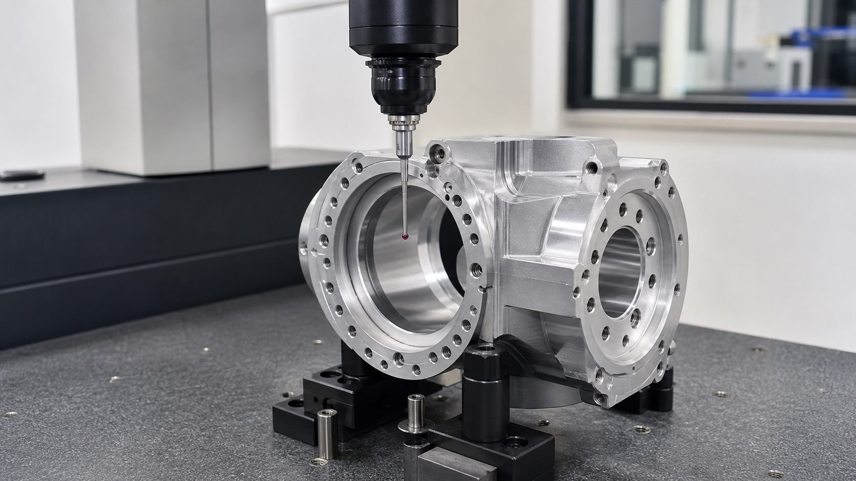
For robot joint motor housings, a useful inspection report should show geometry relationships, not just isolated size values. If the report does not include coaxiality or runout data, the buyer may not see assembly risk until bearings and shafts are installed.
| Inspection item | What to check | Acceptance purpose |
|---|---|---|
| Bore diameter | Size at multiple depths or sections | Confirm bearing fit stability |
| Bore roundness | Roundness or max-min variation | Detect clamp deformation and spring-back |
| Coaxiality | Bore-to-bore relationship to defined datum | Control shaft and reducer alignment |
| End-face runout | Face runout relative to bore axis | Verify axial contact quality |
| Bolt-circle position | Hole group relative to A/B/C datums | Avoid clamping distortion |
| Surface finish | Ra or functional finish on bearing seat | Protect fit, contact and assembly life |
Material and Surface Treatment Notes
Al6061 is practical for many prototype housings because it machines well and controls cost. Al7075 may be reviewed when stiffness, lightweight design or higher strength matters, but stress release and anodizing effects need more attention.
If hard anodizing or coating is required, bearing fits should be planned carefully. Coating thickness can change bore size and edge condition. For tight bearing seats, the buyer and supplier should agree whether inspection is before treatment, after treatment, or after a post-treatment finishing operation.
How OEMach Handles Robot Joint Housings
For robot joint motor housings, OEMach usually separates functional zones from non-functional geometry. Bearing bores, end faces, dowel holes and bolt-circle relationships are treated as critical. Pockets, cable windows, ribs and external shapes are controlled according to assembly clearance and weight requirements.
The machining strategy can combine staged roughing, low-stress clamping, precision boring and CMM inspection. When the part has multiple bore directions or difficult access, 5-axis machining can reduce repeated setups and help preserve datum relationships.
This approach is useful for robot joint prototypes and low-volume builds where the assembly team needs reliable bearing fit, coaxiality and runout data before committing to the next design iteration.
RFQ Checklist for Buyers
| Send this information | Why it matters |
|---|---|
| STEP file | Allows access, wall thickness and fixturing review |
| 2D drawing with datums | Shows bore relationships, runout, hole position and finish requirements |
| Bearing model or fit target | Helps confirm bore tolerance and finish |
| Surface treatment requirement | Prevents coating-related fit changes |
| Assembly stack information | Shows which faces and bores are truly functional |
| Inspection report requirement | Aligns CMM output with buyer acceptance needs |
FAQ
What is the hardest feature in robot joint motor housing machining?
The hardest part is usually not one diameter. It is maintaining bearing bore coaxiality, bore roundness and end-face runout after roughing, clamping, flipping and surface treatment.
Does the housing always need 5-axis machining?
Not always. 5-axis machining is helpful for multi-direction bores, angled features and reduced setup changes. Simpler housings can be machined with 3-axis or 4-axis equipment if datum control is strong.
Should bearing bores be inspected before or after anodizing?
It depends on the fit requirement. If coating thickness affects the bearing seat, the drawing and RFQ should clearly state whether final acceptance is before anodizing, after anodizing or after a finishing operation.
Why does bolt-circle position matter if the bore is correct?
A shifted bolt circle can pull the housing during tightening and change the functional alignment. Hole position should be related to the same datums as the bearing bore.
Can OEMach support prototype motor housings?
Yes. OEMach can support low-volume robot joint motor housings with machining strategy review, bearing-fit planning, CMM inspection and surface-treatment risk review.
Summary
Robot joint motor housing machining should control bearing bores, end faces, bolt circles and locating datums as one assembly system. The best RFQ is not the one with the tightest tolerance everywhere, but the one that marks the real functional features clearly. When coaxiality, runout, fit and inspection requirements are aligned early, prototype assembly becomes faster and rework risk drops.