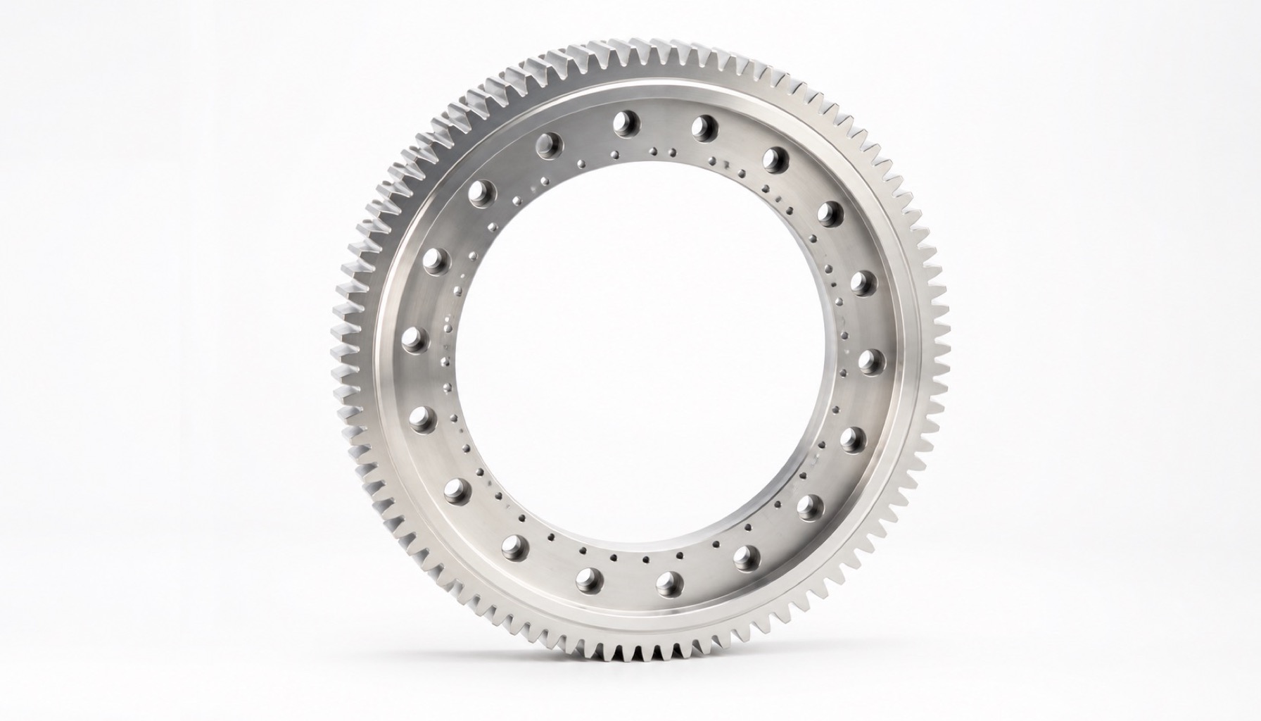
Robot harmonic drive flexspline machining is difficult because the part combines a thin-wall gear ring, precision bore, end face, mounting holes and possible heat-treatment distortion. A flexspline is not a normal ring gear; wall-thickness change and clamping stress can directly affect meshing behavior.
The safer approach is to remove heavy stock first, establish the bore and end-face datum, and then finish the gear ring, bore and face with low clamping force. Final size alone is not enough; roundness, runout, symmetry and spring-back after release must also be reviewed.
For prototype and low-volume harmonic reducer parts, the machining plan should make thin-wall deformation visible before the assembly test.
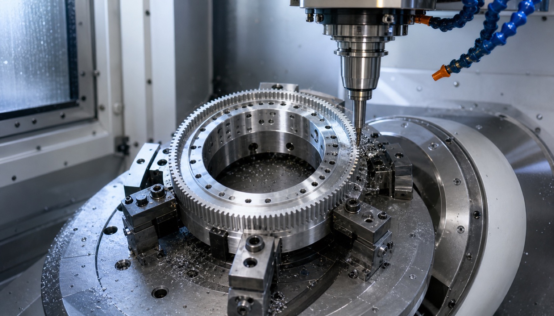
Direct Answer
To control a robot harmonic drive flexspline, manage wall thickness, bore roundness, end-face runout, mounting holes and heat-treatment allowance in one process plan. Thin-wall features should not be finished under heavy clamp load, because the part can rebound after release.
Critical bore, face and thin-wall gear-ring zones can often be process-controlled around +/-0.005 mm to +/-0.01 mm in prototype work, while clearance shapes, lightening holes and non-functional edges can use assembly-based tolerances.
Which Features Affect Meshing Most?
Flexspline quality transfers directly into harmonic drive assembly. A clean-looking ring is not enough. The thin-wall gear ring and bore datum must remain stable, symmetric and repeatable after machining.
| Feature | Main influence | Typical consequence |
|---|---|---|
| Thin-wall gear ring | Meshing stiffness and elastic deformation | Uneven tooth contact or higher noise |
| Bore | Assembly datum and rotation center | Rotational resistance variation or concentricity error |
| End face | Contact with wave generator or adjacent parts | Amplified face runout |
| Mounting hole group | Clamping force and repeat assembly | Local pull after tightening |
| Transition radii | Stress concentration and burr risk | Fatigue risk or assembly scratches |
Common Machining Risks
Flexspline problems do not always appear during first-article visual inspection. If a report only lists bore diameter without roundness, runout and wall-thickness data, the real risk may show up later during assembly or running-in.
| Risk | Cause | Assembly impact |
|---|---|---|
| Uneven gear-ring wall thickness | Roughing and finishing not separated or tool deflection | Unstable tooth contact |
| Poor bore roundness | Excessive clamping force or shifted flip datum | Rotation center offset |
| Large face runout | Face and bore not finished in the same datum logic | Axial wobble after assembly |
| Heat-treatment distortion | Uneven material stress release | Insufficient finishing allowance |
| Hole or tooth-root burrs | Small holes and root edges not deburred properly | Scratches or residual chips during assembly |
Process Route to Reduce Deformation
The process should expose distortion early instead of hiding it until final inspection. Stable stock, balanced stock removal, low-stress fixturing and enough finishing allowance are more important than chasing every dimension in the first setup.
| Process step | Recommended practice | Control purpose |
|---|---|---|
| Blank preparation | Choose stable material and leave even stock | Reduce internal stress and uneven removal |
| Rough machining | Open bore, outside shape and lightening structures first | Release heavy cutting stress |
| Semi-finishing | Correct bore, face and gear-ring datums | Build a stable coordinate system for final cuts |
| Heat treatment or aging | Apply when required by material and strength | Expose distortion trend before final machining |
| Finish machining | Use low clamp force, staged toolpaths and sharp tools | Control roundness, runout and wall-thickness consistency |
| Deburring and recheck | Inspect tooth roots, hole mouths and face edges separately | Prevent scratches and residual chips |
Inspection Data Buyers Should Request
If a report only gives bore diameter, outside diameter and height, it is not enough to judge whether a flexspline is ready for assembly validation.
| Inspection item | What to review | Purpose |
|---|---|---|
| Bore roundness | Multi-section measurement and max-min difference | Confirm stable rotation center |
| Face runout | Measured relative to bore or specified datum | Judge axial assembly risk |
| Gear-ring wall thickness | Measurements at multiple angular positions | Confirm consistent elastic deformation |
| Hole position | Hole group relative to A/B/C datums | Avoid local pull during tightening |
| Post-heat-treatment distortion | Compare key dimensions before and after heat treatment | Verify finishing allowance |
| Burrs and chamfers | Photos of tooth roots, holes and face edges | Prevent scratches and residual chips |
How OEMach Usually Handles These Parts
For a robot harmonic drive flexspline, OEMach typically sets the bore, end face and thin-wall gear ring as critical reference zones. Lightening holes, outside clearances and non-functional edges are managed separately to avoid over-tightening the whole drawing.
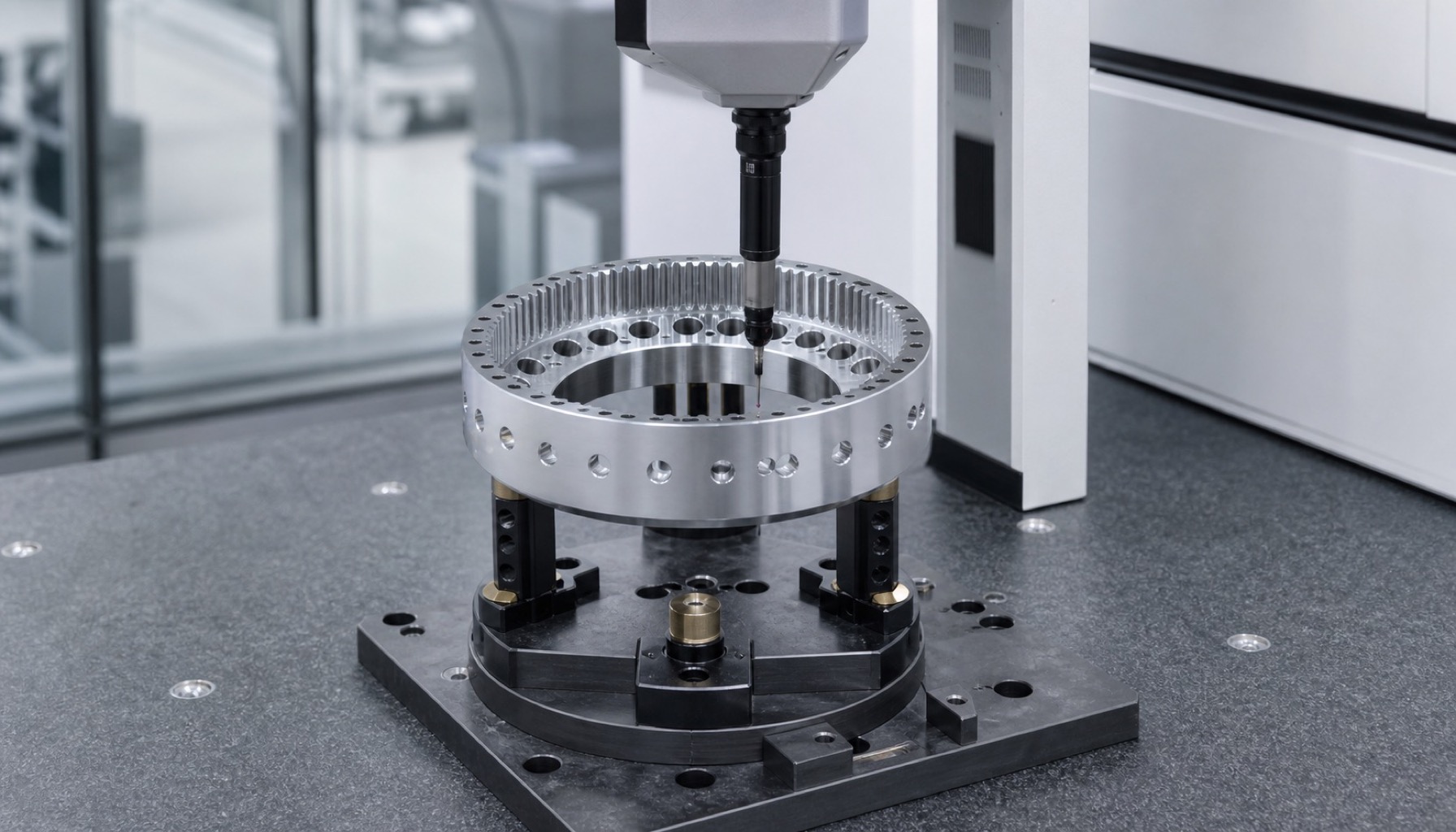
The process uses separated roughing and finishing, low clamping force and staged finishing cuts so the thin-wall gear ring is not distorted by the fixture. After machining, CMM and roundness checks can review bore roundness, face runout, hole position and wall-thickness distribution.
This makes the part easier to validate in low-volume robot joint development, where the supplier must understand thin-wall, high-concentricity and low-stress machining requirements.
Procurement Questions Before Ordering
| Question to ask | Why it matters |
|---|---|
| Are the bore and end face machined in the same datum strategy? | Checks roundness and runout risk |
| How is the thin-wall gear ring protected during clamping? | Evaluates deformation and spring-back risk |
| Are before/after heat-treatment records available? | Makes distortion trend traceable |
| How are tooth roots and small holes deburred? | Avoids scratches and residual chips |
| Can roundness and face-runout data be provided? | Lets engineering judge assembly risk earlier |
| Can low-volume trial production include consistency statistics? | Evaluates future supply stability |
FAQ
What is the most common problem in flexspline machining?
Thin-wall spring-back, poor bore roundness, large face runout, heat-treatment distortion and burrs around holes or tooth roots are common risks.
Does a flexspline always require 5-axis machining?
Not always. Complex multi-face features or many datum transfers benefit from 5-axis machining. Simpler parts can be machined on 3-axis equipment if fixturing and datum control are strong.
Which tolerances should be marked as critical?
Bore roundness, face runout, gear-ring wall thickness and hole position should be marked separately. Prototype work often needs process attention around +/-0.005 mm to +/-0.01 mm for critical areas.
Should dimensions be checked before and after heat treatment?
If heat treatment is part of the material or strength requirement, recording key dimensions before and after heat treatment helps judge distortion and finishing allowance.
Can OEMach machine low-volume flexsplines?
Yes. OEMach can support low-volume harmonic drive flexsplines, thin-wall gear rings and robot joint transmission rings with machining and inspection review.
Summary
Robot harmonic drive flexspline machining should control the thin-wall gear ring, bore roundness, face runout and heat-treatment distortion together. A process that only checks isolated dimensions can still produce meshing noise, unstable rotation resistance and poor batch consistency. Aligning datums, allowance and inspection items early makes prototype validation more reliable.