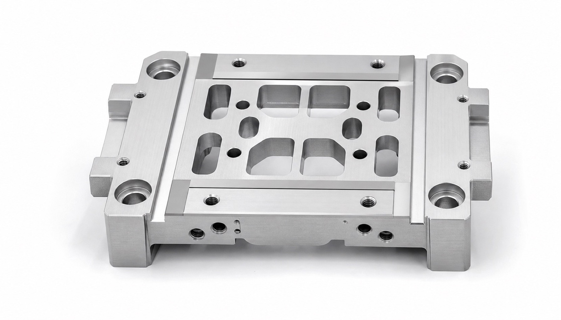
Robot linear guide slider block machining is not only about producing a rectangular aluminum part. The rail mounting face, hole pattern, dowel holes, side datum and bottom reference must be controlled as one functional system.
If the rail face is flat but the hole pattern is not aligned to the same datum, the guide rail can be pulled out of line during tightening. The result may be uneven running resistance, local wear, noise or repeatability drift in the linear module.
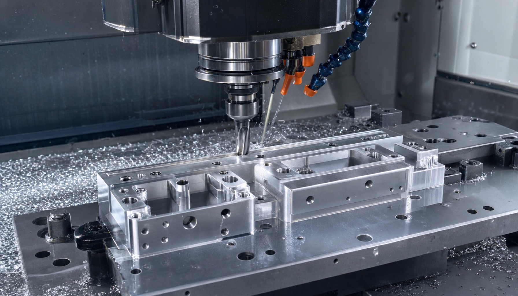
A stable process usually rough-machines the part first to release material stress, then re-establishes the bottom and side datums, and finally finishes the rail mounting face and critical hole pattern in a controlled setup.
Direct Answer
To control a robot linear guide slider block, keep the rail mounting face, side datum, dowel holes and mounting holes in the same datum strategy. Do not treat the hole pattern as a separate drilling operation after the face has already been finished.
For prototype and low-volume parts, critical functional zones can often be process-controlled around +/-0.005 mm to +/-0.01 mm, while lightening pockets, clearance faces and cosmetic edges can use looser general tolerances to avoid unnecessary cost.
Which Features Affect Motion Most?
A slider block can pass basic outside-dimension inspection and still fail in the module. The important question is whether the rail seating face, hole group and side reference remain stable relative to each other after machining and tightening.
| Feature | Main influence | Typical consequence |
|---|---|---|
| Rail mounting face | Rail seating and slider running resistance | Binding, noise or local wear |
| Mounting hole pattern | Rail clamping force distribution | Rail pulled sideways after tightening |
| Dowel holes | Repeat assembly and maintenance recovery | Position shift after disassembly |
| Side datum face | Rail parallel relationship | Linear module travel direction error |
| Lightening pockets and clearances | Local stiffness and machining deformation | Micro-deformation or interference after loading |
Common Machining Risks
Most slider block problems appear during travel testing rather than at first-article visual inspection. If the guide rail feels different at different stroke positions, the face and hole datum relationship should be reviewed first.
| Risk | Cause | Assembly impact |
|---|---|---|
| Uneven rail face | Datum not corrected after roughing or uneven clamping force | Rail may sit partially unsupported |
| Hole pitch drift | Accumulated error from flipped setups | Rail is pulled out of line after tightening |
| Poor side-face squareness | Side datum and mounting face processed separately | Parallel relationship becomes unstable |
| Rib or pocket spring-back | Too much material removed from lightening areas | Local deformation after assembly |
| Hole-mouth burrs | Threaded holes and dowel holes not deburred correctly | Scratches during tightening or locating |
Process Route for Better Flatness and Position
The rail face should not be finished too early. If heavy pocketing, flipping or aggressive clamping happens later, the reference face can move. A better route separates roughing, datum repair and final finishing.
| Process step | Recommended practice | Control purpose |
|---|---|---|
| Blank preparation | Leave stock on the rail face, side datum and hole group | Keep correction allowance for functional areas |
| Rough machining | Remove large pockets and non-critical material first | Release material stress early |
| Datum establishment | Use the design bottom and side faces as a unified reference | Bring machining datums closer to assembly datums |
| Rail face finishing | Use light finishing cuts and controlled cutter direction | Protect flatness and seating stability |
| Hole pattern machining | Complete dowel holes and mounting holes in the same datum logic | Reduce hole position error |
| Deburring and recheck | Inspect threaded holes, dowel holes and rail slots separately | Avoid scratches and locating interference |
Inspection Items Buyers Should Request
A report that only lists length, width and hole diameter is not enough for a slider block. The inspection should show how the critical features relate to the assembly datum.
| Inspection item | What to review | Purpose |
|---|---|---|
| Rail face flatness | Multiple points across the rail seating area | Confirm stable rail contact |
| Mounting face parallelism | Measured to the bottom or defined datum | Verify module assembly relationship |
| Hole position | Hole group relative to A/B/C datums | Avoid rail pull during tightening |
| Dowel hole size and position | Diameter, roundness and position | Support repeat assembly |
| Side datum squareness | Measured to the rail mounting face | Control rail parallel relationship |
| Burrs and chamfers | Hole mouths, slots and edge photos | Prevent assembly scratches |
How OEMach Usually Handles These Parts
For a robot linear guide slider block, OEMach typically defines the rail mounting face, dowel holes and mounting hole group as critical functional zones. Lightening pockets, clearance faces and external cosmetic edges are managed separately based on assembly space.
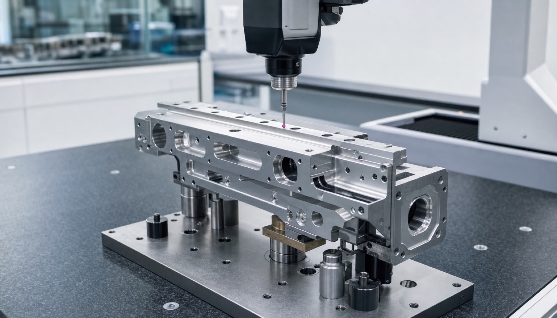
The machining plan uses separated roughing and finishing, hole-group machining under the same datum logic, and light finishing on the rail face. After machining, CMM inspection can verify rail face flatness, hole position, mounting face parallelism and side datum squareness.
This approach helps reduce rework during prototype assembly because the supplier and buyer are reviewing the same functional relationships, not only isolated dimensions.
Procurement Questions Before Ordering
| Question to ask | Why it matters |
|---|---|
| Will the rail mounting face be inspected as a critical surface? | Confirms the supplier understands motion risk |
| Are the hole group and rail face machined in one datum strategy? | Reduces hole position risk |
| Which datum is used for dowel-hole inspection? | Avoids mismatch between report and assembly datum |
| Could lightening pockets cause rail-face spring-back? | Reviews stiffness and deformation risk |
| How are holes and rail slots deburred? | Prevents scratches during tightening and locating |
| Can you provide a first-article CMM report? | Allows engineering to review risk before assembly |
FAQ
What is the most common problem in slider block machining?
Uneven rail faces, hole position drift, poor side datum squareness, pocket spring-back and burrs around holes are common issues that can affect guide rail motion.
How tight should rail face flatness be?
It depends on guide rail size, slider spacing and load. For prototypes, mark the rail face, dowel holes and hole pattern as critical features, then review the required range with the supplier.
Should I choose Al6061 or Al7075?
Al6061 is often practical for prototypes because it balances cost and machinability. Al7075 can be reviewed for higher stiffness or lightweight requirements, but stress and surface-treatment size changes must be considered.
Why is hole position more important than single hole diameter?
The guide rail is constrained by the relationship of the whole hole group. A hole can have the right diameter while the group still pulls the rail out of alignment.
Can OEMach machine low-volume slider blocks?
Yes. OEMach can support low-volume robot linear guide slider blocks, linear module bases and slide table structural parts with process and inspection review.
Summary
For robot linear guide slider blocks, assembly performance depends on rail face flatness, hole position, mounting face parallelism and side datum consistency. Controlling these relationships during first-article machining helps engineering and procurement judge whether a prototype is ready for module assembly.