
O-ring grooves and sealing faces are small features, but they often decide whether a CNC machined part can hold pressure, block dust, prevent coolant leakage or protect electronics. A cover plate, manifold, valve body, cooling plate or instrument housing may look correct from the outside while still failing because the groove depth, corner radius, flatness or surface finish was not defined clearly before manufacturing.
For overseas engineering buyers, O-ring details should be reviewed before RFQ. If a supplier only sees a 3D model, they may machine the visible shape but not understand the sealing function. A complete drawing should identify the O-ring size, groove width, groove depth, compression target, sealing face, surface roughness, flatness and whether the seal is static or dynamic. These details affect machining time, inspection method and final assembly risk.
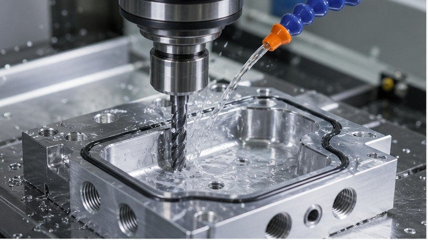
The first point is the seal type. Most CNC machined housings and plates use static seals, where the O-ring is compressed between two fixed surfaces. Dynamic seals, such as shafts or sliding parts, require different design rules and usually tighter control of surface finish and wear. If the application includes fluid pressure, vacuum, coolant, dust protection or repeated opening, the drawing should explain the functional requirement instead of only showing the groove geometry.
Groove width and depth must match the O-ring material and compression ratio. A groove that is too shallow may over-compress the seal and make assembly difficult. A groove that is too deep may not compress the O-ring enough and can leak. The correct value depends on O-ring cross-section, material hardness, pressure direction and whether the seal sits in a face groove or radial groove. Buyers should avoid leaving the supplier to guess these values from the 3D model.
Corner radii and tool access also matter. A machined groove cannot have perfectly sharp internal corners unless a special process is used. End mills leave a radius, and very small tools increase cost and risk. If the O-ring design allows a reasonable corner radius, the groove becomes easier to machine and inspect. For rectangular or custom groove paths, designers should check whether the cutter can enter and exit without marking the sealing land.
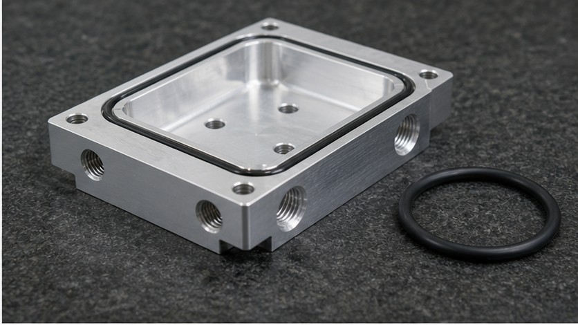
Flatness is one of the most important inspection items for sealing faces. Even if the groove is correct, a warped cover plate or uneven sealing land can create local leakage. Large aluminum plates, thin covers and parts with heavy material removal may deform after machining. If a sealing face must remain flat after anodizing or other finishing, that requirement should be written clearly. The supplier may need balanced machining, stress relief or final skim cutting to control distortion.
Surface finish should be specified where the O-ring contacts the metal. A surface that is too rough can damage the seal or create leakage paths. A surface that is too polished may not be necessary and can add cost. For most static seals, a controlled machined finish is enough, but the exact requirement depends on pressure, fluid, O-ring material and assembly method. Buyers should mark the sealing surface instead of applying a tight finish to the whole part.
Ports, threaded holes and intersecting channels need burr control. Many sealing parts include fluid passages, side ports or screw holes near the groove. Burrs at intersections can cut the O-ring, trap particles or prevent the cover from seating. If the part is used for fluid control, medical equipment, cooling systems or clean assemblies, internal deburring and cleaning should be included in the RFQ.
Surface treatment can change sealing behavior. Anodizing, hard anodizing, plating or passivation may affect groove dimensions, roughness and the contact face. Some sealing lands should remain uncoated, while others can be coated if the design allows it. If inspection should be done after surface finish, say so. Otherwise, the supplier may inspect the machined part before finishing while the buyer expects final coated dimensions.
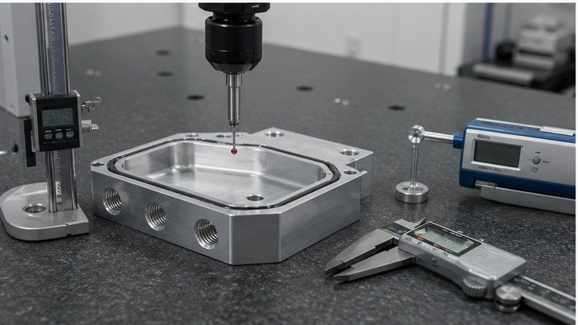
Inspection should focus on functional sealing features. Typical checks include groove width, groove depth, sealing face flatness, surface roughness, port thread fit and the position of bolt holes around the seal. A CMM, depth gauge, height gauge or roughness tester may be needed depending on tolerance. If a leak test is required after assembly, define pressure, medium, duration and acceptable leakage level before production.
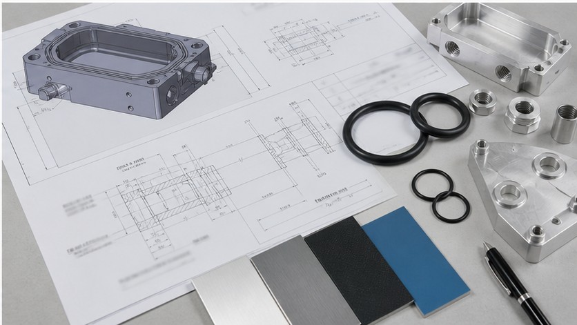
A strong RFQ package for sealed CNC parts includes STEP or STP files, 2D drawings, O-ring standard, groove dimensions, seal material, pressure or environment notes, surface finish, flatness, coating requirements, inspection report needs and cleaning requirements. Mark which face is the sealing face and which holes clamp the cover. This helps the supplier quote the real manufacturing and quality scope, not only the part shape.
OEMach supports custom CNC machining, CNC milling, CNC turning, 5-axis machining, prototypes and low-volume production for sealed housings, manifolds, cooling plates and precision covers. When O-ring grooves and sealing faces are defined clearly before quotation, the final parts are easier to inspect, assemble and approve. The goal is not only a clean groove, but a reliable seal that works with the material, finish and assembly process.