
Threaded holes look like small details on a CNC drawing, but they often decide whether an assembly goes together smoothly. A thread that is too shallow, too close to an edge, poorly called out or difficult to inspect can create rework even when the rest of the machined part is accurate. For overseas engineering buyers, threaded-hole requirements should be reviewed before RFQ so the supplier can quote machining, tooling, inspection and risk correctly.
The first item to define is the thread standard. Metric threads such as M3, M4, M6 and M8 are common in automation equipment, robotics and fixtures. Inch threads may be required for North American assemblies. Pipe threads, fine threads and special inserts need clearer notes because they affect tools and inspection gauges. A drawing should state thread size, pitch, depth, whether the hole is through or blind, and any countersink or counterbore requirement.
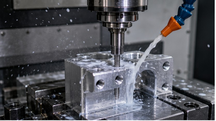
Thread depth deserves special attention. A blind tapped hole needs enough pilot depth beyond the usable thread because the tap or thread mill requires clearance at the bottom. If a drawing only says M6 x 1.0 but does not define effective thread depth, the supplier may choose a standard depth that may not match the bolt engagement needed by the assembly. For load-bearing joints, buyers should define the required full thread engagement and confirm whether the material is aluminum, stainless steel, titanium or plastic.
Material changes the thread strategy. Aluminum is easy to tap, but threads can strip if repeated assembly, high torque or vibration is expected. Stainless steel is stronger but harder on tools and more sensitive to galling. Titanium requires careful cutting conditions and good chip control. Engineering plastics may need different engagement length because the material is softer. If the part will be assembled many times, thread inserts such as Helicoil-style inserts may be a better choice than direct tapped aluminum threads.
Thread inserts are useful when strength, repairability or wear resistance matters. They are common in aluminum housings, fixture plates, robotic parts and lightweight components that use steel fasteners. If inserts are required, the drawing should specify insert type, installed depth, locking or non-locking style and whether the supplier should install them or only machine the preparation holes. Without clear notes, the quote may include tapping only, while the buyer expects completed installed inserts.
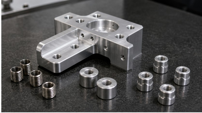
Designers should check edge distance and wall thickness around threaded holes. A tapped hole too close to an outside wall may break through, deform or leave weak material. A side threaded hole that intersects another bore can create burrs or incomplete thread form. For compact parts, CAD models can hide these problems until machining starts. It helps to review cross-sections and mark any areas where a partial thread or intersecting hole is acceptable.
Chamfers and lead-ins make assembly easier. A small entrance chamfer protects the first thread and helps screws start cleanly. However, if the chamfer is too large, it can reduce useful thread length. Counterbores and countersinks should be defined with diameter, angle or depth. If a screw head must sit flush, the drawing should show the exact requirement instead of relying on a general note.
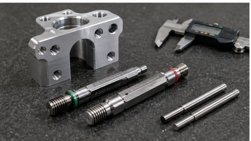
Inspection should match the thread function. Standard threaded holes are commonly checked with go/no-go gauges. Critical thread position may also require CMM or positional inspection relative to datums. If a threaded hole locates a precision assembly, the buyer may need to report both thread acceptance and hole position. If only thread fit is checked, a hole can pass the gauge but still be slightly mislocated for assembly.
Burr control is another practical issue. Tapping and thread milling can leave burrs at entry, exit or intersecting features. For fluidic parts, medical equipment, robotics and optical fixtures, burrs can affect sealing, cleanliness or assembly feel. Drawings should specify deburring requirements when threaded holes intersect pockets, bores or internal channels. If no burrs are allowed inside a blind feature, the supplier needs to plan tools and cleaning accordingly.
Surface finishing can affect threads. Anodizing, hard anodizing, plating and passivation may change thread fit or leave coating inside the hole. Some threads should be masked; others should be tapped after coating; some may accept coating if the fit allows it. Buyers should define whether thread gauges apply before or after surface finish. This is especially important for aluminum parts that receive hard anodizing or for stainless parts that require passivation after machining.
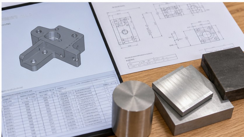
A good RFQ package for threaded CNC parts includes STEP or STP files, 2D drawings, material, finish, thread callouts, thread depth, insert requirements, inspection needs and target quantity. If certain threaded holes are critical for torque, repeated assembly or sealing, mark them clearly. This allows the machining team to choose tapping, thread milling, insert installation and inspection methods before quoting.
OEMach supports custom CNC machining, CNC milling, CNC turning, 5-axis machining, prototypes and low-volume production for overseas buyers. When threaded-hole requirements are defined clearly, quotes become more accurate and final parts are easier to assemble. The best result is not just a clean thread, but a reliable fastening feature that works with the material, finish and inspection plan.