
CNC machining tolerances define how much variation is allowed from the nominal size on a drawing or 3D model. For custom parts, they are not just numbers for inspection. They influence machining strategy, fixture design, tool choice, cycle time, inspection method, cost and delivery risk.
A common mistake is to make every dimension tight because the part feels important. That usually increases cost without improving function. A better approach is to identify which features control assembly, motion, sealing, alignment or appearance, then apply tighter tolerances only to those features.
This guide explains how buyers and engineers can specify CNC machining tolerances clearly before requesting a quote, so suppliers can price the real requirement instead of guessing.
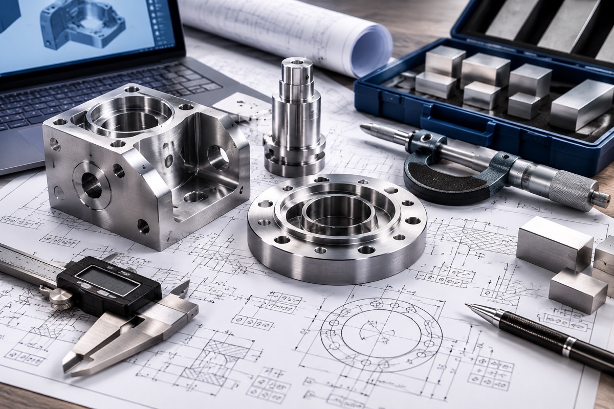
What CNC Machining Tolerances Really Mean
A tolerance is the allowed variation around a nominal dimension. If a drawing calls out 25.00 +/-0.05 mm, a part may be accepted between 24.95 mm and 25.05 mm. The smaller the allowed range, the more carefully the process must be controlled.
Tolerance also depends on what is being measured. A simple outside length is easier to hold than the position of multiple holes across two setups. A flatness requirement on a thin wall may be harder than a linear size on a thick block. Because of this, the same tolerance value can have different manufacturing impact depending on geometry.
| Tolerance type | Typical use | Manufacturing impact |
|---|---|---|
| Linear size | Lengths, widths, thicknesses and slot widths | Usually straightforward unless the feature is thin, deep or hard to access |
| Hole diameter | Dowel holes, bearing bores, clearance holes | May need reaming, boring, special tooling or post-machining inspection |
| Position | Hole patterns and locating features | Depends on datum scheme, setup stability and inspection method |
| Flatness | Mounting faces, sealing faces, sensor pads | Can be difficult on thin or relieved parts |
| Parallelism / perpendicularity | Guide faces, assembly interfaces and sliding features | Often requires careful fixturing and datum control |
| Surface roughness | Sealing, sliding, cosmetic or fluid-contact surfaces | May require finishing passes or secondary processing |
Do Not Apply Tight Tolerances Everywhere
A drawing with tight tolerances on every dimension often tells the supplier that every feature is critical. That makes programming, machining and inspection more conservative. It can also create unnecessary rejection risk, especially on prototype parts where the real assembly requirement is still being tested.
Instead, separate the part into functional and non-functional areas. Critical features should be controlled clearly. Non-critical geometry can use general tolerances, model-based tolerance notes or standard shop capability. This makes the drawing easier to review and keeps inspection focused on what affects performance.
| Feature | Tolerance priority | Reason |
|---|---|---|
| Dowel pin holes | High | Control location and repeatable assembly alignment |
| Bearing bores | High | Control fit, roundness and press-in behavior |
| Sensor mounting faces | High | Affect flatness, contact and calibration stability |
| Sealing grooves | High | Affect leakage, compression and edge condition |
| Clearance pockets | Medium or low | Often only need enough space for neighboring parts |
| Hidden outside profiles | Low | Usually do not affect assembly if clearance is adequate |
| Cosmetic chamfers | Low to medium | Need consistency, but rarely need precision tolerance unless exposed |
Practical Tolerance Levels for Custom CNC Parts
There is no single tolerance that fits every CNC part. Material, size, geometry, machine access, surface finish and inspection method all matter. However, it is useful to think in tolerance levels when preparing an RFQ.
For many custom metal parts, general tolerances are enough for non-critical geometry. Precision tolerances should be reserved for mating features, controlled fits and dimensions that affect the final product.
| Tolerance level | Typical use | Cost and inspection note |
|---|---|---|
| General tolerance | Non-critical outer profiles, clearance areas, rough dimensions | Most cost-efficient and fastest to inspect |
| +/-0.10 mm | Common machined dimensions and simple interfaces | Often reasonable for many aluminum and steel parts |
| +/-0.05 mm | Assembly features, slot widths, controlled heights | Requires clearer process control and inspection |
| +/-0.02 mm | Precision fits, bearing locations, dowel-related dimensions | May require stable fixturing, finishing passes and CMM or gauges |
| Tighter than +/-0.01 mm | Special precision features only | Should be reviewed case by case for process, material and measurement method |
How Tolerances Affect Cost and Lead Time
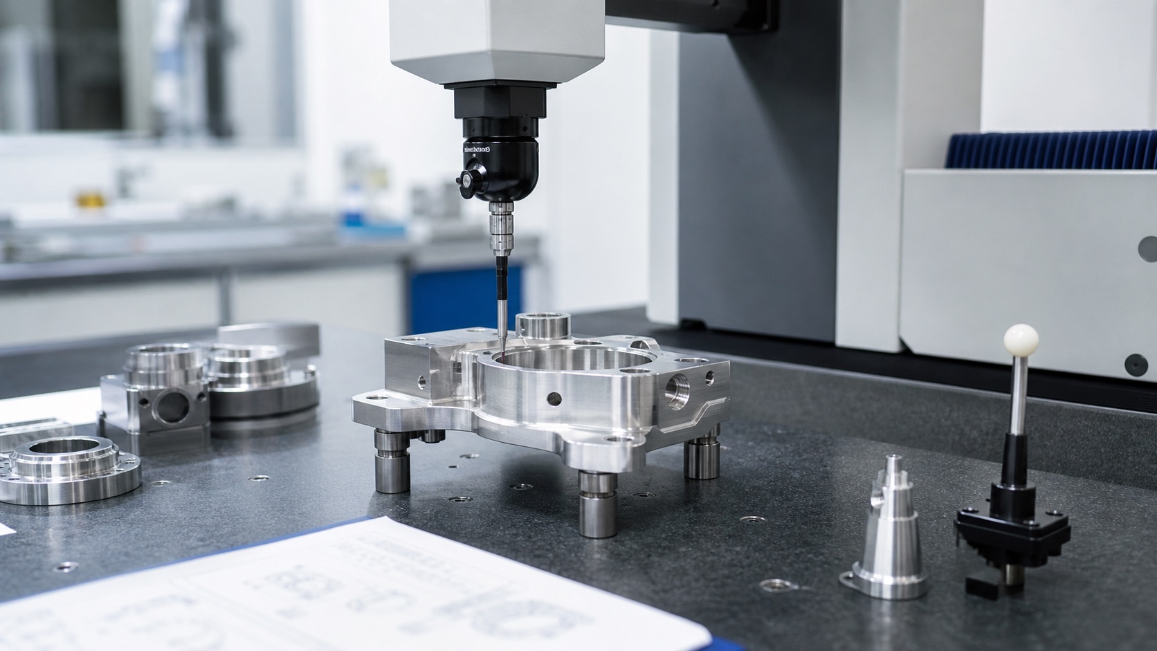
Tighter tolerances usually mean more process control. The machinist may need slower finishing passes, more stable fixtures, tool wear compensation, intermediate checks, special gauges or CMM measurement. If the tolerance is applied to many features, inspection time can grow quickly.
Lead time can also change. A supplier may need to confirm fixture strategy, order special tools, reserve inspection equipment or add first article inspection. For urgent prototypes, it is important to tell the supplier which dimensions must be controlled immediately and which can be relaxed for early fit checks.
| Requirement | Possible added work | Buyer question |
|---|---|---|
| Tight hole tolerance | Reaming, boring, plug gauge or CMM check | Is the hole for clearance, pin location or bearing fit? |
| Flatness on a thin plate | Stress control, special fixturing and face inspection | Is the full face functional or only local pads? |
| Position tolerance across many holes | Datum planning and CMM program | Which holes define alignment and which are clearance? |
| Fine surface roughness | Extra finishing pass or polishing | Is roughness needed for sealing, sliding or appearance? |
| Full dimensional report | More inspection and documentation time | Which dimensions need documented results? |
Material and Geometry Change What Is Realistic
Tolerance capability is not only a machine question. Aluminum, stainless steel, titanium, brass, copper, PEEK and POM behave differently during cutting and measurement. Thin walls can move after material is removed. Plastics can deform with clamping force or temperature. Stainless steel can hold heat and create tool wear.
Large parts also need different thinking from small parts. A +/-0.02 mm tolerance on a short pin hole may be realistic. The same tolerance across a long thin frame may require special process planning, stress relief or a different inspection method.
| Situation | Tolerance risk | Practical control |
|---|---|---|
| Thin-wall aluminum | Deflection and chatter during machining | Stage roughing, support walls and inspect after release |
| PEEK or POM parts | Clamp deformation and temperature sensitivity | Use sharp tools, low clamping force and stable inspection temperature |
| Stainless steel | Heat, burrs and tool wear | Control cutting parameters and finish critical features carefully |
| Long parts | Accumulated error and fixture distortion | Use clear datums and avoid unrealistic full-length tight tolerances |
| Multi-face parts | Setup transfer error | Use 5-axis access or a strong datum strategy where needed |
How to Mark Tolerances on Drawings
A 3D model alone is rarely enough for precision CNC machining. The model gives geometry, but the 2D drawing explains what matters. A useful drawing should show general tolerance, critical dimensions, datums, thread details, surface roughness, finish notes and inspection requirements.
When possible, avoid vague notes such as all dimensions critical. Use specific callouts for the features that matter. If GD&T is used, make sure the datum scheme reflects how the part is assembled or measured. A good datum scheme reduces disagreement between supplier and buyer.
| Drawing item | What to include |
|---|---|
| General tolerance block | Default tolerance for dimensions without individual callouts |
| Critical dimensions | Tighter tolerance only on functional features |
| Datums | Stable reference faces or holes that match assembly use |
| Hole notes | Diameter, depth, thread type, reamed holes, countersinks and chamfers |
| Surface roughness | Only where roughness affects sealing, sliding, appearance or contact |
| Inspection notes | CMM report, first article inspection or gauge requirements where needed |
What to Send for an Accurate Tolerance Review
Suppliers can quote more accurately when they understand both the geometry and the function. If the RFQ includes only a STEP file with no tolerance notes, the supplier must guess which dimensions are critical. That can lead to conservative pricing or repeated engineering questions.
A better RFQ explains the purpose of the part. For example, if two holes locate a robot sensor bracket, mark those holes as critical. If the outside profile only clears a cover, it may not need tight control. This information helps reduce cost without weakening the design.
| RFQ information | Why it helps |
|---|---|
| STEP/STP file | Allows toolpath, setup and material removal review |
| 2D drawing | Shows tolerances, datums, threads, finish and inspection notes |
| Application context | Explains which dimensions affect assembly or function |
| Critical feature list | Helps engineering focus DFM and inspection planning |
| Material and finish | Changes machining behavior and final dimensional review |
| Quantity and lead time | Affects setup strategy, inspection scope and cost structure |
How OEMach Handles Tolerance Review
OEMach reviews CNC machining tolerances before quoting custom precision parts. We check which features are critical, whether the tolerance level matches the material and geometry, how many setups are needed, and what inspection method is appropriate.
When a tolerance appears tighter than the function requires, we can suggest a more practical callout. When a feature is genuinely critical, we keep it visible in the machining plan and inspection plan. This helps buyers control cost while still protecting fit, alignment, sealing and product reliability.
FAQ
What is a normal CNC machining tolerance?
For many non-critical dimensions, general shop tolerances or around +/-0.10 mm may be sufficient. Precision features may require +/-0.05 mm, +/-0.02 mm or tighter depending on geometry and function.
Should I put tight tolerances on every dimension?
No. Tight tolerances should be applied to functional features such as fits, datums, sealing surfaces, bearing bores and locating holes. Non-critical geometry can usually use general tolerance notes.
Does a tight tolerance always increase CNC cost?
Usually yes. Tight tolerances can add machining time, setup planning, inspection, documentation and rework risk.
Do I need a 2D drawing if I already have a STEP file?
For precision parts, yes. The STEP file shows geometry, but the 2D drawing communicates tolerances, datums, threads, surface finish and inspection notes.
When should I request a CMM report?
Request a CMM report when critical dimensions, positional relationships, flatness or GD&T requirements must be documented for acceptance.
Summary
Good CNC machining tolerance control starts with clear priorities. Do not make every dimension tight. Identify functional features, define realistic tolerance levels, use clear datums, and send both STEP files and 2D drawings. A practical tolerance strategy can reduce cost, shorten lead time and improve supplier communication while protecting the features that determine part performance.