
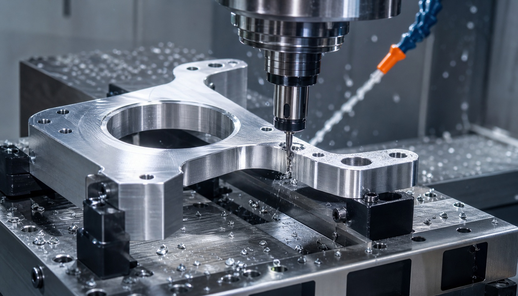
Whether burrs on robot precision parts affect dimensions depends on burr location, the removal method and the function of the part. A light break edge on a normal outside corner usually does not damage a critical dimension. But burrs near bearing bores, dowel pin holes, thread starts, sensor mounting faces or sealing features can affect assembly clearance, hole-edge radius, sealing contact and final dimensions after surface finishing.
The real risk is not simply that burrs exist. The risk is whether they appear on a functional boundary. If a small rolled edge remains around a locating hole, a dowel pin may not enter smoothly. If deburring creates an oversized chamfer, the effective support area at the hole mouth becomes smaller. On robot assembly parts with tolerance levels around +/-0.005 mm to +/-0.02 mm, these small edge conditions can become real assembly problems.
At OEMach, deburring and chamfer requirements for low-volume robot parts are normally planned into the machining process instead of being left as a last-minute cleanup step. This helps align appearance, assembly behavior and inspection criteria.
Which Burrs Can Affect Assembly?
Burr problems on robot parts are often discovered during assembly rather than visual inspection. Hole mouths, slots and sharp edges need special attention, especially when the drawing does not define the chamfer or break-edge requirement clearly.
| Burr location | Possible effect | Inspection focus |
|---|---|---|
| Dowel pin hole mouth | Pin insertion is rough or location shifts | Clean hole edge and consistent chamfer |
| Bearing bore edge | Press-fit misalignment or collapsed hole edge | Bore size, roundness and entrance chamfer |
| Thread start | Cross-threading or abnormal torque | Complete thread lead-in and no chips left inside |
| Sensor mounting face | Unstable contact or calibration drift | Mounting flatness and edge residue |
| Seal groove edge | O-ring damage or air/oil leakage | Groove radius and remaining burrs |
| Cable pass-through hole | Cable jacket abrasion | Smooth and safe edge around the opening |
Why Deburring Can Also Change Dimensions
Deburring is not simply a matter of making every edge as clean as possible. Some precision edges must remain sharp as datums, some edges need a uniform chamfer and some hole mouths only allow a very small break edge. The process should first separate functional edges from non-functional edges, then choose the correct removal method.
| Deburring method | Advantage | Dimensional risk |
|---|---|---|
| Manual scraper | Flexible for low-volume and irregular edges | Uneven force can create inconsistent chamfers |
| Light ceramic blade finishing | Friendly to aluminum and engineering plastics | Over-processing can enlarge the edge radius at holes |
| In-machine chamfer tool | Good consistency for repeat production | Incorrect program settings can cut into functional edges |
| Vibratory tumbling | Useful for batch cosmetic edges | Not suitable for high-precision holes or local functional faces |
| Blasting or shot peening | Improves overall surface feel | May affect small holes, thin walls and surface roughness |
| Electrochemical or chemical deburring | Suitable for complex internal holes | Material and removal amount must be tightly controlled |
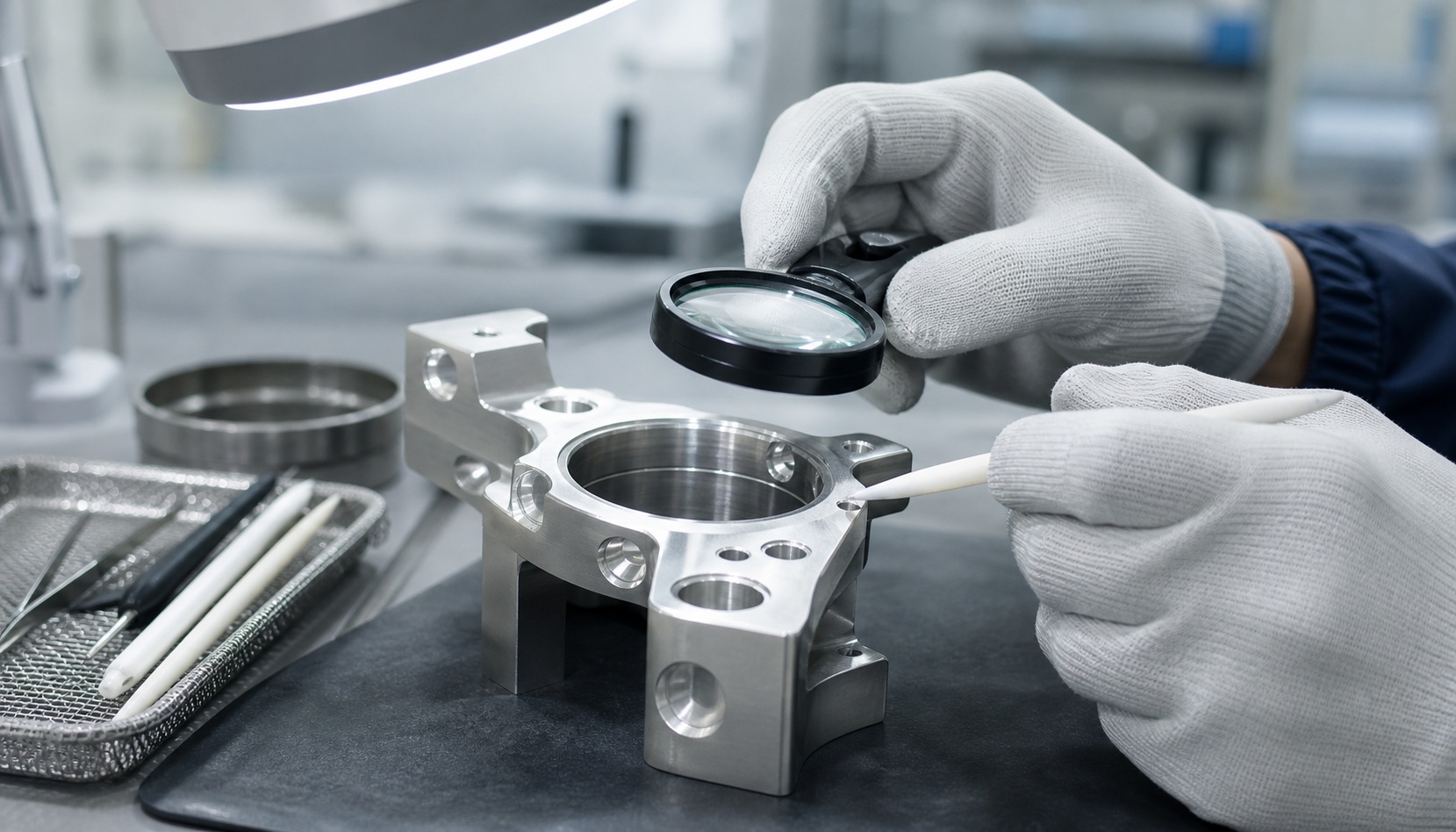
How to Specify Chamfers and Deburring on Drawings
Many rework disputes come from the vague note "deburr." If the part includes locating holes, bearing bores, seal grooves or sensor mounting faces, the key boundaries should be defined. Even simple notes such as C0.2 or R0.2 max are more reliable than leaving the edge condition open to interpretation.
| Drawing note | Best use | Key point |
|---|---|---|
| Deburr and break sharp edges | Normal non-functional outside edges | Acceptable for low-risk areas, but not very precise |
| C0.2-C0.5 | Cosmetic edges, cable holes and normal assembly edges | Defines a measurable chamfer range |
| Hole mouth C0.1 max | Locating holes and precision fit holes | Limits over-chamfering and protects effective hole support |
| R0.2 max | Seal grooves and sliding edges | Prevents cutting damage while limiting excessive radius |
| Do not polish functional face | Datums, contact faces and sealing faces | Prevents manual finishing from damaging flatness |
| Recheck critical holes after deburring | High-precision holes and bearing bores | Confirms edge work has not changed hole size |
Material Differences in Burr Removal
Material choice changes the deburring strategy. Applying an aluminum deburring method directly to PEEK or POM can cause compression marks, whitening or local deformation. Applying a light plastic-part approach to stainless steel can leave hard burrs behind.
| Material | Common burr behavior | Recommended handling |
|---|---|---|
| Al6061 | Relatively easy to deburr; soft surface | Clean hole mouths before anodizing and avoid pressure marks |
| Al7075 | Higher strength and sharper edges; tool condition matters | Use sharp tools and in-machine chamfering for consistency |
| PEEK | Tough material that can form fine stringy burrs | Use light clamping, sharp tools and avoid heat deformation |
| POM | Burrs can fold over; dimensions are temperature-sensitive | Control cutting heat and avoid heavy manual pressure |
| Stainless steel | Hard burrs and longer finishing time | Control hole-mouth burrs and chips at thread starts |
How OEMach Controls Burrs and Dimensions
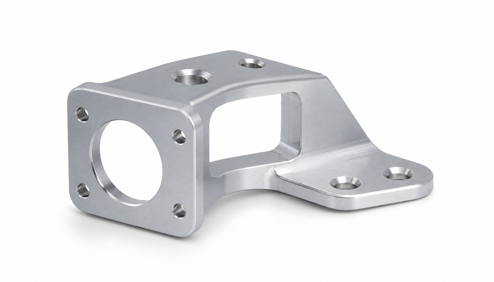
For a robot sensor mounting bracket, OEMach may program normal outside edges with an in-machine chamfer of about C0.2 while keeping tighter edge control near locating holes and the sensor mounting face. After machining, the part is not aggressively polished as one whole piece; functional areas and non-functional areas are treated separately.
For thin-wall Al7075 regions, OEMach combines 5-axis machining, staged toolpaths and vacuum-assisted fixturing to reduce machining distortion before light hole-edge finishing. For PEEK materials, clamping force is reduced and sharp tools are used to minimize stringy burrs, so manual deburring does not pull dimensions out of range.
Finally, critical holes and mounting surfaces are checked with CMM, pin gauges or plug gauges where appropriate. This removes burrs that affect assembly without over-finishing precision boundaries.
Procurement Inspection Checklist
If a supplier only says that parts will be deburred but cannot explain which edges are chamfered in-machine, which edges are lightly finished by hand and which functional faces must not be touched, consistency is difficult to guarantee in small-batch delivery. For robot precision parts, burr control should be part of the manufacturing plan, not a repair step before shipment.
| Inspection question | Purpose |
|---|---|
| Are there rolled burrs at locating holes or bearing bores? | Confirm pins and bearings can be inserted or pressed smoothly |
| Does the chamfer size match the drawing? | Avoid over-deburring that reduces effective support area |
| Are there manual polishing marks on datum faces? | Protect flatness and contact performance |
| Are chips left inside threaded holes? | Prevent abnormal assembly torque |
| Are cable holes and seal grooves smooth? | Avoid cable jacket or seal damage |
| Were critical dimensions rechecked after deburring? | Confirm cosmetic edge work did not change functional dimensions |
FAQ
Are burrs normal after machining robot precision parts?
Small burrs are common after CNC machining. The key is burr location and removal method. Burrs near functional holes, seal grooves and sensor mounting faces must be controlled carefully.
Can deburring make a hole larger?
Excessive deburring can enlarge the entrance chamfer and reduce the local support area. Precision holes should have a clear chamfer limit and be rechecked after finishing.
Is it enough to write only "deburr" on the drawing?
It can be enough for ordinary outside edges, but key hole mouths, sealing faces and locating edges should define C0.2, R0.2 max, or no-polish requirements.
Is PEEK deburring the same as aluminum deburring?
No. PEEK is tough and can form stringy burrs or deform with heat. It needs sharp tools, light clamping and more careful manual finishing.
What should buyers check during burr acceptance?
Focus on rolled burrs at hole mouths, chamfer consistency, polishing marks on datums, chips in threads and remeasurement records for critical dimensions.
Summary
Burrs on robot precision parts should not be treated as a small cosmetic issue. Hole-mouth burrs can affect dowel pins, bearings and sensor installation; edge burrs can affect cables, sealing and surface finishing. At the same time, deburring must not be excessive, because oversized chamfers and collapsed hole edges can damage key fit dimensions. Planning toolpaths, chamfer allowances, manual inspection and CMM spot checks during manufacturing is more reliable than last-minute rework.