
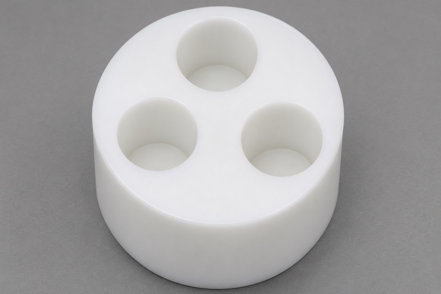
Define the three blind-bore component
The proposed parking puck is a short solid cylinder of natural unfilled POM-C for an inert diagnostic pipette fixture. It has flat top and bottom faces and exactly three equal plain blind bores arranged in a triangular pattern from the top. Each bore has a defined flat floor and stops before the bottom face. There is no central fourth hole, thread, through-hole, flange or inserted hardware. This guide concerns CNC machining and inspection of the component, not pipette calibration, contamination control or clinical suitability. The designer must define the actual contact envelope and whether any identified part may touch a bore floor.

Specify POM-C rather than an unspecified acetal substitute
POM-C and POM-H are different acetal material types, so the required grade and stock form should be stated explicitly. Natural white appearance is not material identification. Keep source records associated with the puck through blank preparation, turning, bore machining and any approved subsequent work. Do not assume that a trade name, previous order or photograph authorizes substitution. Chemical exposure, cleaning, biological suitability and diagnostic workflow requirements need application-specific review. A material certificate identifies what was supplied within its scope; it does not establish finished bore dimensions or qualify an assembled pipette parking system.
Separate usable bore depth from tool reach
Define the plane from which depth is measured and the floor region that terminates the specified cylindrical bore. A tool's axial travel is not automatically the accepted depth. Entry chamfers, bottom transitions and any tool marks must be treated according to the drawing. The proposed floors are flat rather than a deliberately conical drill-point end. If a route requires a different bottom shape, obtain approval instead of calling the deepest point the functional depth. Specify any usable cylindrical length separately where it differs from overall cavity depth, so both the machining and inspection plans address the same requirement.
Preserve the material below each bore
Review bore depth together with overall thickness and the remaining floor requirement. Correct depths measured from the top do not by themselves establish the required floor thickness if the external thickness is wrong. Identify any direct minimum-material control and its measurement basis. The component must remain blind: accidental breakthrough or a substitute through-hole would change the proposed geometry. Do not assign a floor dimension from this article or infer strength from a visible pale bottom. The designer must establish the requirement, and the supplier should clarify how the planned process and inspection can address it before cutting stock.
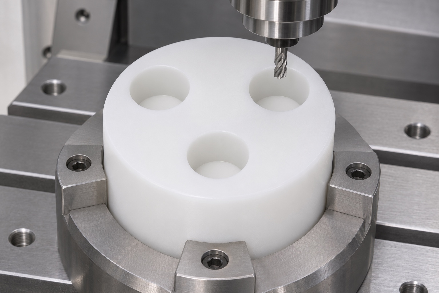
Define the three-hole layout and its references
State bore diameters and the required center relationships, including the triangular layout or other drawing-defined pattern. A circular outside surface can establish useful geometric references, but it does not alone provide an absolute rotational index. If the fixture requires clocking, define the relevant reference arrangement rather than inventing an extra feature. Equal nominal bore diameters do not prove correct spacing or centering. Identify which surfaces locate the puck during measurement and which merely hold it. The plan should evaluate the actual positional relationships instead of relying on three reference pieces that appear to fit simultaneously.
Plan circular preparation and bore machining together
A candidate route can prepare the outside cylinder and faces, then machine the three blind bores in an appropriately supported setup. The actual order depends on grade, stock proportions, access and tolerances. Review how references transfer between operations and how the remaining walls and floors are protected from excessive restraint. The proposed geometry does not prescribe a universal drill, end mill, feed or waiting interval. If a particular operation is selected to create the flat floors, document the reason and any relevant finishing allowance. A plausible machine image is not evidence that this route has already produced accepted parts.
Consider restraint and the released polymer geometry
Support the puck without assuming that dimensions measured under strong clamping represent its supplied condition. Define the agreed restraint, conditioning and inspection state. Removing material at three locations can change the support and process response, but no amount of distortion is predicted here. If development observations lead to another sequence or stabilization step, record the conditions and verify the revised route. Avoid treating every polymer grade as interchangeable or using an unexplained waiting time as a guarantee. Final acceptance should address the completed component after relevant operations, not an earlier circular blank with different internal geometry.
Control bore entries and bottom transitions
Remove unwanted burrs or loose material while preserving bore size, usable cylindrical length, depth and floor geometry. A broad entry blend can alter where a reference seats, and aggressive work at the bottom transition can affect local remaining material. Specify edge requirements and inspection exclusions rather than polishing until the cavities look similar. A white, smooth-looking bore does not prove cleanliness or chemical compatibility. Keep tools and handling consistent with the intended supply state. Any proposed relief, tapered bore or changed floor shape requires drawing approval and revised inspection criteria instead of being introduced informally during finishing.
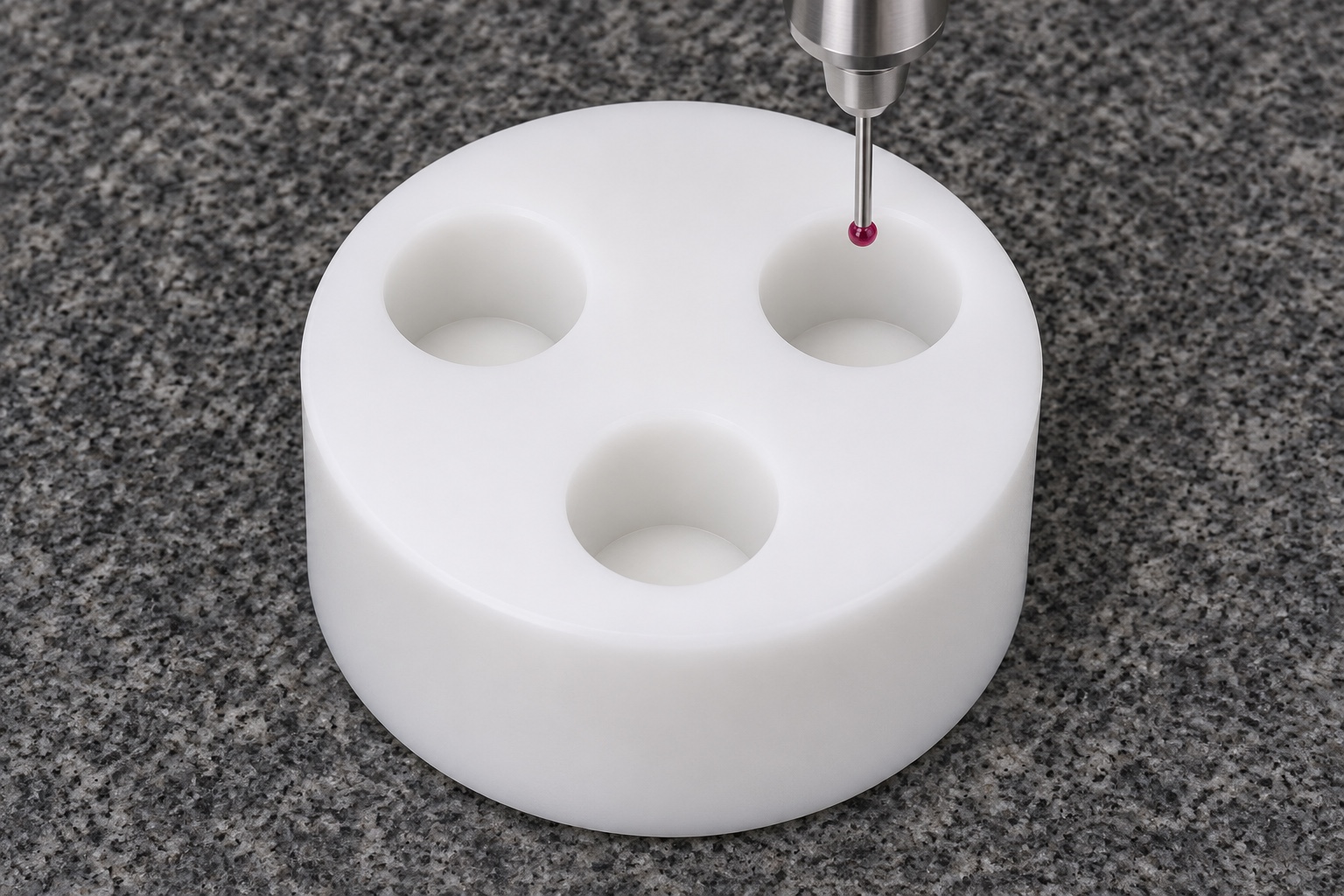
Use suitable methods for depth and bore geometry
A depth result depends on its reference plane, probe access and contact location on the floor. A probe resting on a bottom transition may answer a different question from one contacting the specified flat region. Bore size and layout need their own suitable evaluation; a depth reading cannot establish those features. State the method's capability and uncertainty relative to actual tolerances. If remaining material is calculated from external thickness and cavity measurements, identify the inputs and relevant relationships. First-article evidence should distinguish observations, calculations and nominal values, not treat a photograph of three cavities as a measurement report.
Limit inert pipette-reference observations
An agreed check with clean, controlled inert references may reveal entry interference, obvious clearance or an unintended contact region. Identify the reference revision and whether floor contact is allowed. Such an observation does not establish pipette accuracy, delivered volume, contamination control, cleaning efficacy or clinical suitability. It also does not replace dimensional inspection of the puck. Avoid introducing active liquid handling or clinical samples merely to support a machining article. Any functional or hygiene requirement belongs to the responsible workflow's separately defined evaluation and cannot be inferred from a parking reference that appears to stand securely in one cavity.
Clean and protect the blind cavities for supply
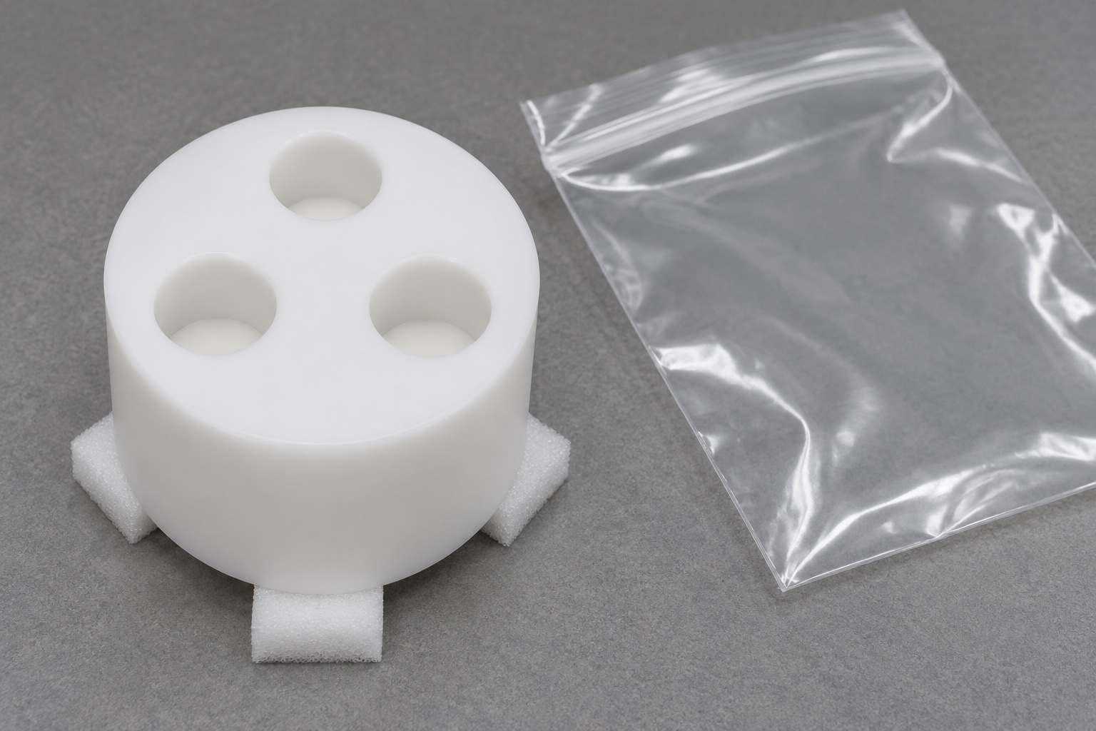
Specify the actual outgoing cleaning condition, residue requirements and verification included in the order. Blind cavities need handling that avoids retained loose material and protects the entries and flat floors. Keep the puck separated from loose hardware and maintain identification without uncontrolled marks on contact surfaces. An ordinary protective pouch is not a validated sterile barrier, a cleaning result or a transport qualification. State any additional process explicitly and retain its evidence separately. Receiving inspection should be able to connect the correct material and drawing revision to the supplied component without assuming that natural color demonstrates cleanliness or grade identity.
Prepare a complete plastic machining RFQ
Provide the current drawing, model, quantities, exact POM-C grade and supplied-state requirements. Include bore diameter, defined depth reference, floor shape, remaining material, layout, entry treatment and measurement condition. Ask for DFM review of access, support, reference transfer and chip removal from the cavities. Specify inspection evidence and protective packaging while keeping pipette calibration, liquid-handling performance and cleaning validation separate where required. Clear inputs support a focused quotation for custom three-blind-bore parking pucks without inventing tolerances, standard fits or diagnostic performance from the material name and component appearance.
FAQ
Are the three cavities through-holes?
No. They are blind bores with flat floors and material remaining underneath. A through-hole, conical floor or extra central hole would change the proposed geometry and require explicit approval.
Is tool travel the accepted bore depth?
Not automatically. Define the top reference plane, floor contact region and treatment of entry and bottom transitions. The machining command and the inspected usable depth are related but are not interchangeable evidence.
Does correct depth prove the remaining floor thickness?
No. External thickness and relevant geometric relationships also matter. Specify the required remaining material and an appropriate inspection basis instead of assuming that top-referenced depth alone establishes it.
Does a circular outside define absolute hole-pattern clocking?
Not by itself. Define any necessary rotational reference or mating arrangement. Do not invent an angular acceptance characteristic that the specified reference system cannot establish.
Can POM-H replace POM-C because both are acetal?
Not without approval. Specify the exact required material type and grade. Similar appearance, a trade name or a previous order does not establish interchangeability for the current drawing and application.
Does an inert reference fit prove pipette calibration?
No. It supports only the agreed mechanical observation. Volume accuracy, contamination control, cleaning and workflow suitability require separate procedures and evidence for the actual system.

tanghangyun@oemach.com