
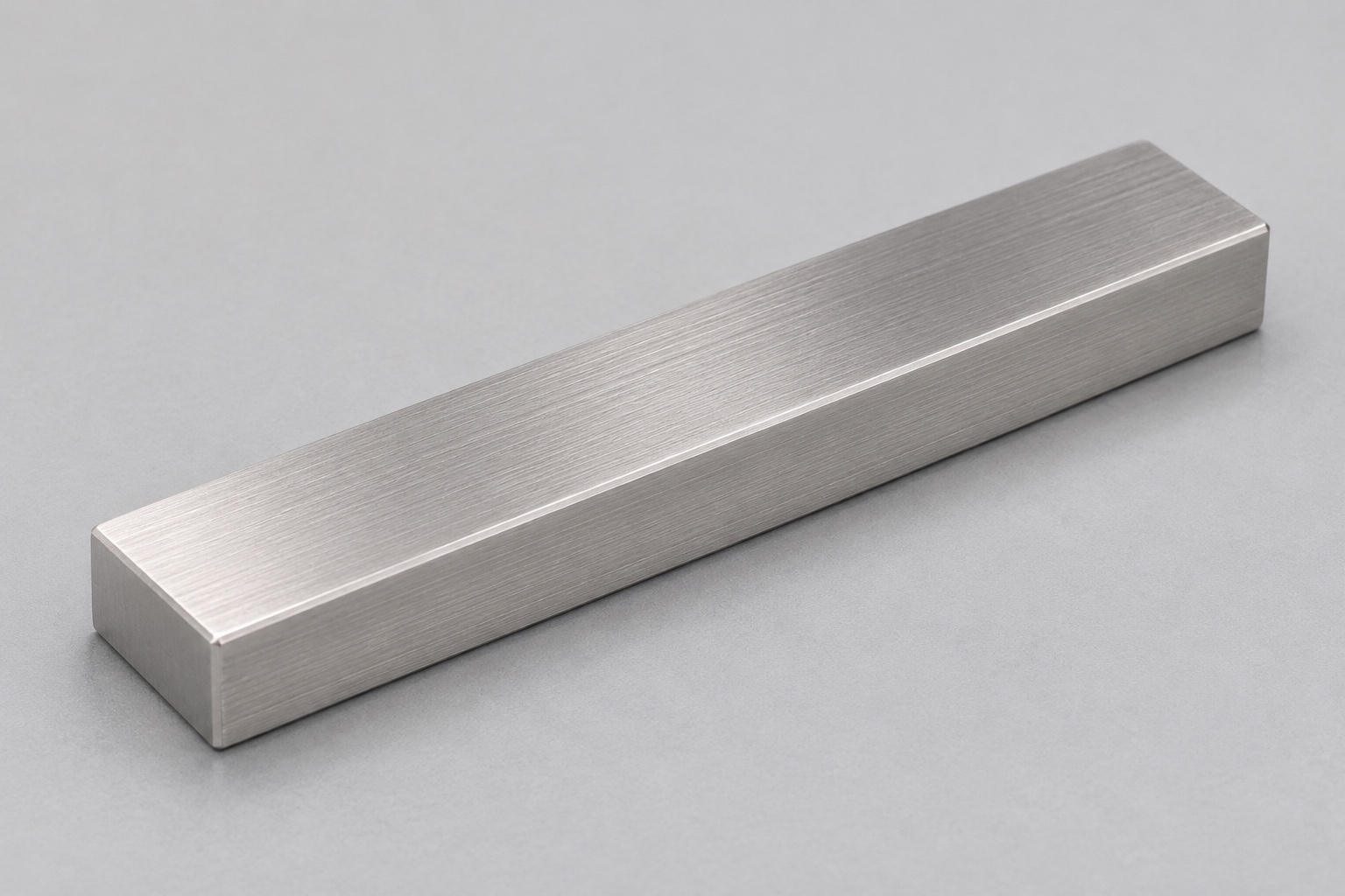
Define the key and the actual locating task
A rectangular datum key can provide defined contact surfaces within a separately designed endoscope assembly fixture. The proposed component is a solid 316L rectangular bar with flat top and bottom, two straight long sides and two flat ends. Small edge chamfers are permitted only as defined by the drawing. It has no holes, slots, grooves, steps, rounded ends or attached hardware. This article concerns precision CNC milling and inspection of that component, not an achieved assembly accuracy. The fixture designer must identify which faces locate, which seat and which provide clearance; the familiar appearance of a rectangular key cannot establish those responsibilities by itself.

Separate working width from general outside size
Identify the long faces that establish the working width and define the region where that width applies. A measurement near one end may not represent the entire contact length if local form or taper matters. Small edge treatments should not be mistaken for the functional width. Clarify whether the interface requires a size control, geometric control or both, using the drawing's actual acceptance scheme. Do not assign a standard key fit solely from the part name. A supplier needs the controlled mating interface or explicit requirements rather than an instruction to make a bar that seems to slide into an available slot.
Define height and usable seating regions
The distance between top and bottom must be connected to the intended support arrangement. Identify whether the bottom seats across its full area or on specified contacts and whether the top acts as a stop, clearance surface or another interface. Nominal height does not establish every local face relationship. A broad manual edge blend can reduce usable contact even if a central thickness reading remains acceptable. State any excluded edge zones and the relevant measurement locations. These details allow the milling and inspection plans to address the same physical features instead of treating overall height as a substitute for all seating requirements.
Distinguish flatness from parallelism
Flatness concerns the form of an individual surface, while parallelism relates a feature to a specified reference. Sweeping the upper face while the lower face rests on a surface plate does not automatically isolate the upper face's independent flatness. The setup and reference condition influence what is being evaluated. Define the actual drawing characteristic and choose a method capable of addressing it. Opposite-face distance readings also should not be reported as every possible form or orientation result. A useful inspection record describes support, alignment, measurement coverage and evaluation rather than labeling all variation simply as flatness.
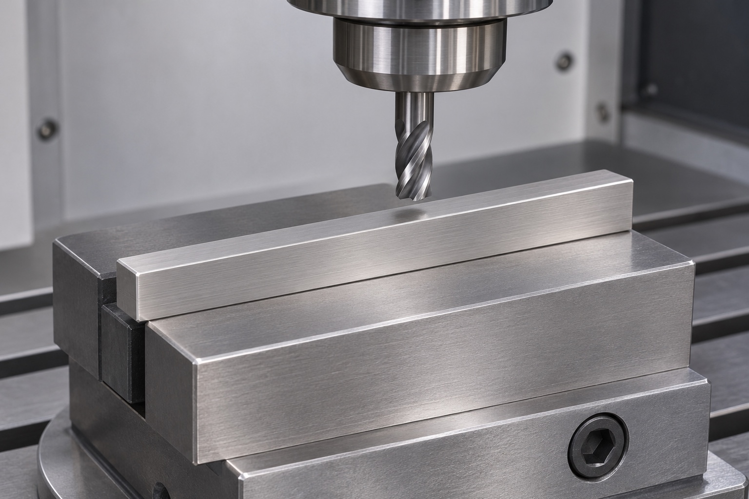
Keep the ends and chamfers outside ambiguous acceptance
Specify length between the intended end faces and clarify any end orientation or usable contact requirement. The proposed part has flat ends, not semicircular ends associated with some other key forms. Chamfers must not remove a required locating region or become an uncontrolled alternative end shape. If tool access or assembly needs another relief, resolve it during drawing review. A photograph cannot authorize an extra slot, a rounded end or a change in contact length. The end treatment and long-face requirements should therefore be reviewed together before quoting, particularly where the key enters a controlled mating recess.
Maintain material identity and finish requirements
Specify the exact 316L requirement, stock form and supporting source records. Keep identification linked through cutting, milling, edge treatment, cleaning and any approved subsequent process. A satin appearance is not proof of alloy identity, passivation or validated cleanliness. If marking a functional surface is prohibited, use controlled records and containers instead of an unapproved mark. A material certificate does not establish finished dimensions. Any corrosion exposure, chemical compatibility, sterilization or patient-contact requirement belongs to its own defined evaluation and cannot be inferred merely because the key is stainless steel and used around medical equipment.
Plan milling around the reference transfer
A candidate route prepares appropriate flat references and coordinates the long sides, top, bottom and ends. Review how the blank is supported, how much material is left for later operations and how references are recovered after a setup change. Clamping a narrow bar securely does not by itself preserve its released geometry or all face relationships. Tool access and holding allowance must suit the actual proportions. If an additional finishing process is necessary for a drawing requirement, define and quote it explicitly rather than assuming CNC milling alone proves every requested condition. No universal cutting parameters or achieved tolerances are supplied here.
Control release and final edge work
Inspect the relevant final condition after operations that can affect the working faces. Restraint during machining may mask a condition that becomes apparent only when the key is released, so the measurement state must be agreed. Deburring should remove unintended sharp material without broadly polishing away functional width or seating regions. Protect finished faces during transfer and avoid gripping them without an appropriate plan. A visually tidy edge does not demonstrate safe handling, roughness or full geometric conformity. Any proposed change to chamfers, contact zones or operation sequence should be documented and reviewed before it becomes a repeat-production assumption.
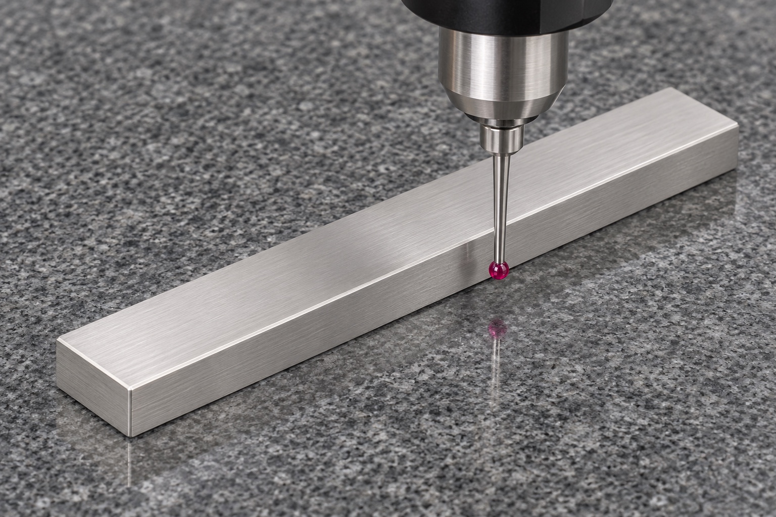
Build a feature-specific first-article plan
Connect each controlled characteristic to drawing revision, material identity, final state, method and actual result. Relevant checks may include working width over the specified region, height, length, face form, orientation, chamfers and surface condition. A two-point size reading can answer a size question without proving the complete surface form. Select measurement capability and access before manufacture, especially where the bar's narrow contact regions complicate support. Do not copy nominal CAD dimensions into measured-result fields. Where a method has an uncertainty or coverage limitation, resolve it before declaring acceptance rather than hiding it behind a general claim of precision inspection.
Keep inert fit observations supplementary
An agreed check in an unpowered fixture may identify interference, entry difficulty or an incorrectly understood contact surface. Record the key and mating reference revisions, support and observation conditions. A satisfactory hand fit does not establish positioning repeatability, retention force, wear life, endoscope alignment or clinical performance. The mating recess and fixture restraint also influence the outcome. Treat the observation as supplementary to dimensional acceptance, not as permission to ignore a failed requirement. Any system performance target needs a separately designed evaluation of the complete relevant assembly rather than an inference from one key that appears to fit.
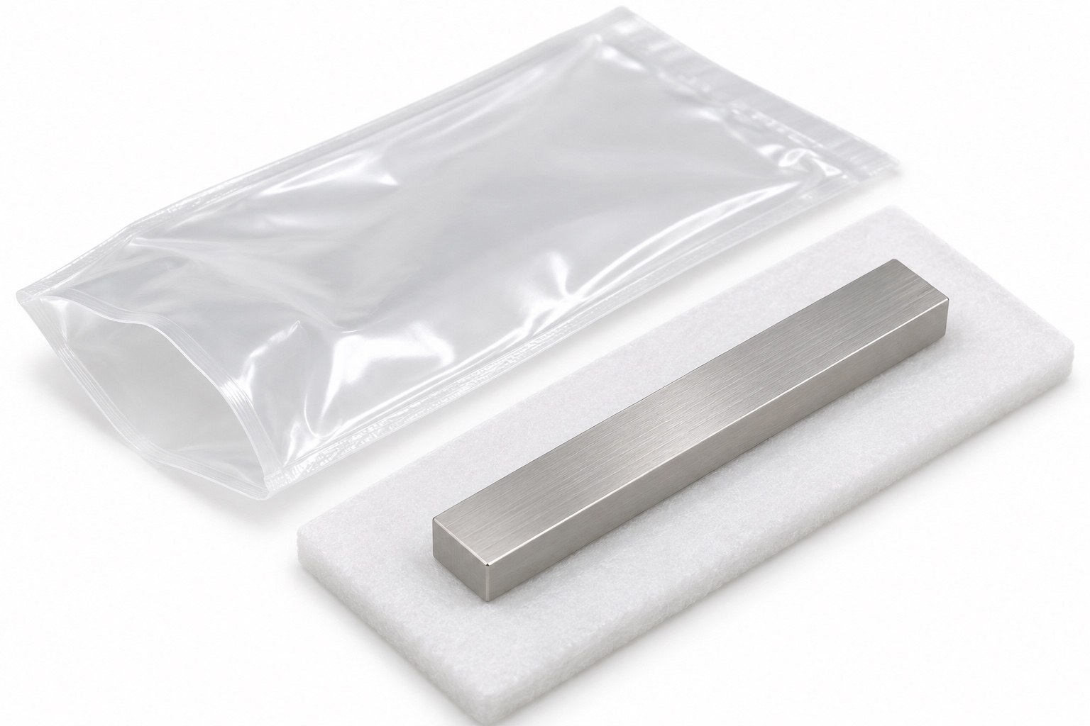
Protect the long faces through supply
Define the outgoing cleaning condition and any residue limits included in the order. Separate keys so edges cannot mark neighboring working faces, and preserve the material and revision link through the package. Protective supports should not leave uncontrolled contact damage on a surface later used as a datum. An ordinary pouch is not a sterile barrier, a validated cleaning result or a qualified transport system. Those requirements need their own specified evidence if actually requested. Receiving inspection should be able to identify the correct orientation and acceptance records without adding labels or marks to prohibited functional regions.
Prepare a focused datum-key RFQ
Provide the current drawing, model, quantities, material specification and intended supplied surface state. Identify working faces, width and height controls, usable contact length, end geometry, references, chamfers and inspection condition. Ask for DFM review of workholding, setup transfer, edge treatment and measurement access. Specify any additional finishing, traceability and protective packaging rather than treating them as automatic medical machining services. These inputs support a comparable quotation for a custom 316L rectangular datum key while keeping fixture accuracy, cleaning qualification and endoscope-system performance separate from the component manufacturing evidence.
FAQ
Does the term datum key imply a standard fit?
No. The drawing must define working faces, dimensions, geometric controls and the mating interface. A familiar name or a sample slot does not authorize an assumed standard fit or acceptance rule.
Can one width reading release the entire key?
Not if requirements also concern other locations, surface form or orientation. Define the measurement region and characteristic. A local size reading should not be reported as complete evidence for every working-face requirement.
Is a supported upper-face sweep always a flatness test?
No. The reference and support condition determine what is evaluated. Relating an upper face to a supporting lower face can address a parallelism question rather than independently isolating the upper face's flatness.
Are rounded ends included in this proposed geometry?
No. The key has flat ends with only specified small edge treatments. A rounded end, extra groove or relief would be a design change requiring approval and corresponding inspection requirements.
Does an inert fit prove endoscope alignment?
No. It supports only the defined mechanical observation. Repeatability, force, wear, instrument alignment and clinical suitability require separate evaluation of the relevant assembly and conditions.
What should the quotation include?
Supply drawing revision, model, quantities, exact 316L requirements, working faces, size and geometry controls, end treatment, finishing, inspection condition and packaging. Define fixture performance or cleaning validation as additional scope where needed.

tanghangyun@oemach.com