
Start with the single-piece mounting geometry
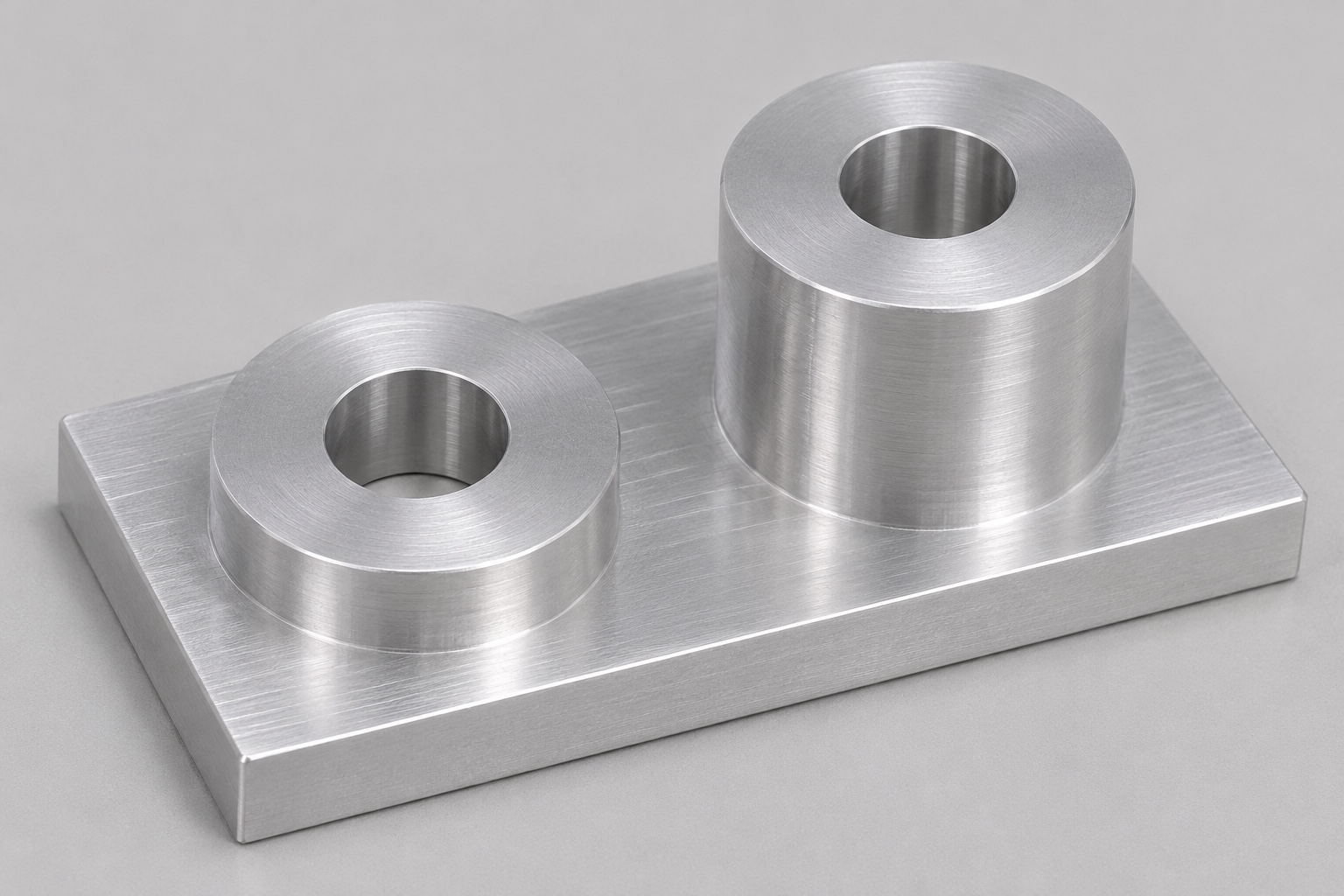
The proposed plate supports a discussion of inert service-fixture interfaces around dialysis equipment, not a wetted fluid path or a functioning treatment device. It has a flat rectangular base and two integral cylindrical bosses arranged along its length. The bosses have equal nominal outside diameters but intentionally different heights. Each has one centered plain through-bore continuing through the base, giving two holes in total. There are no threads, slots or attached fasteners in the defined component. Before requesting precision CNC milling, specify the mating arrangement and which surfaces locate, support or merely provide clearance. Appearance alone cannot establish those roles.

Define a base reference that represents installation
If the underside is the intended support, identify it in the datum scheme and specify how it is seated during measurement. Secondary references should locate the plate consistently without contradicting the assembly's actual contacts. A convenient exterior edge is not automatically a functional datum. The inspection plan should distinguish restraint used to hold the part from references used to evaluate it. Excessive clamping can conceal a condition that appears only after release. Record the support arrangement and agreed inspection state so that the reported boss heights and bore locations have a clear physical meaning for the completed component.
Treat unequal heights as a controlled relationship
The two boss tops are deliberately not coplanar. Define each required height from the agreed base reference and clarify any direct requirement on their height difference. Independent height tolerances and a difference tolerance may describe overlapping acceptance conditions; review them together. Do not ask a supplier to make both tops level simply because they are mounting features. Conversely, a correct difference alone does not prove that either absolute height is correct. The drawing should explain which characteristics govern the intended interface and avoid redundant or contradictory controls. This makes a quotation more meaningful than a general promise of tight machining tolerances.
Separate top-face form from boss height
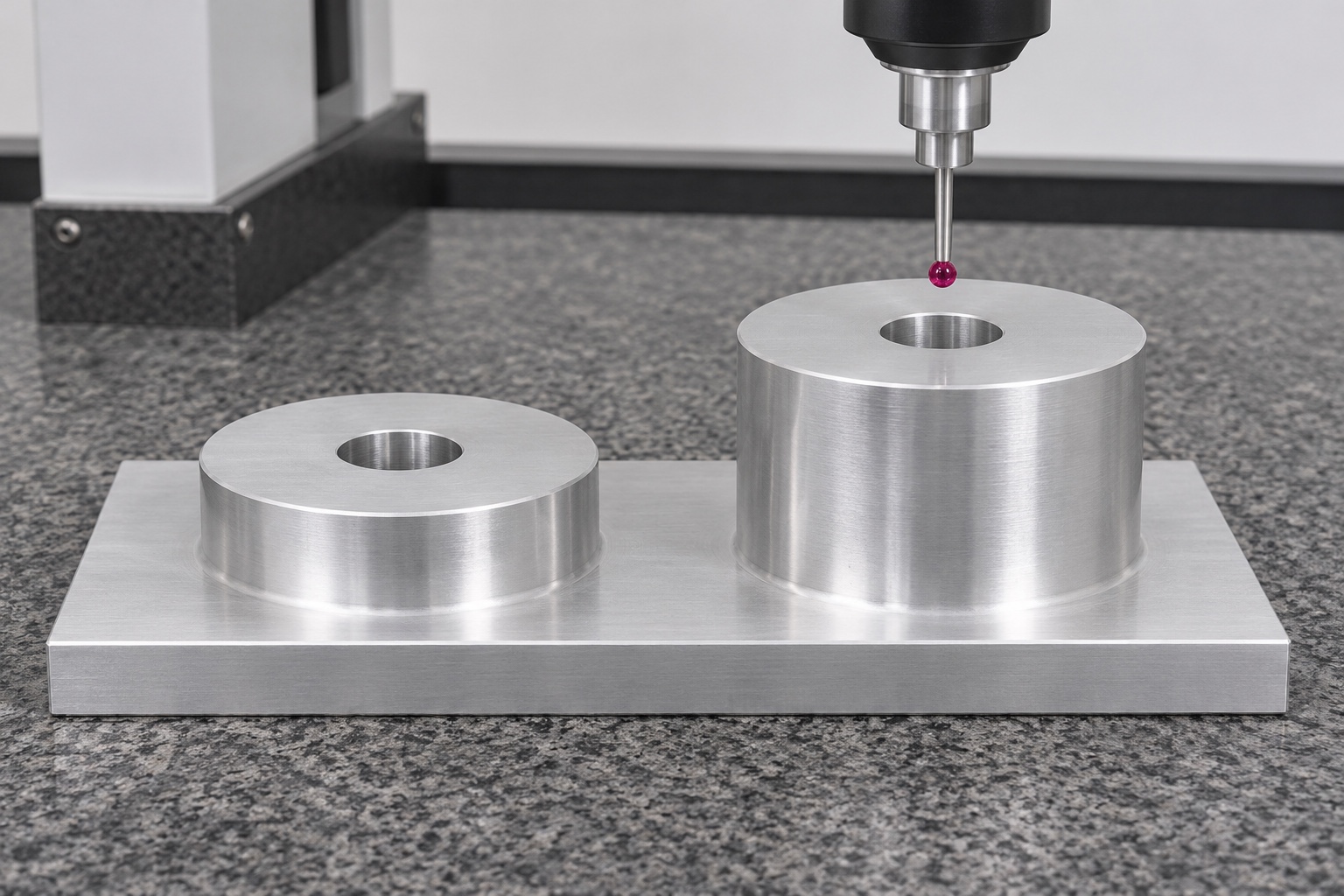
A height result at one point does not establish the flatness or orientation of the entire annular top. Define the relevant contact zone around each bore and exclude only the edge regions actually permitted by the drawing. If a top face needs an orientation relationship to the base, specify that relationship separately from its nominal height. Local form can matter even where the average height appears correct. Select inspection coverage accordingly rather than measuring whichever point is easiest to reach. A reflective surface or a photograph of a probe above a boss cannot establish any of these characteristics by itself.
Locate the through-bores from the approved references
The drawing should define bore size, positions and any required axis relationship to the plate and boss geometry. Two screws passing through the holes would not prove all those requirements. Likewise, equal outside boss diameters do not establish correct bore spacing or centering. Review the wall remaining between each bore and its boss exterior where the interface requires it. Hole entry and exit treatments should remain distinct from usable cylindrical length. The supplier needs to know whether the bores locate a reference, clear a fastener or serve another defined purpose, without inventing a standard fit from their appearance.
Specify 6061 material and any finishing sequence
Identify the required 6061 aluminum condition and supporting material documentation. The alloy designation alone is not the full purchase specification, and a previous order's condition should not be assumed. A single-piece route begins with enough stock for the taller boss and base, but stock selection and allowance still need process review. If anodizing or another finish is requested, state affected areas, masking needs and whether dimensions apply before or after it. A uniform finish does not demonstrate electrical insulation, cleaning compatibility or suitability for operating dialysis equipment. Those application claims require evidence beyond the material and machining record.
Plan milling to preserve the base-to-boss relationship
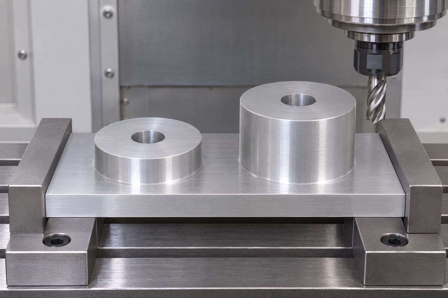
A candidate CNC milling sequence establishes useful references and removes surrounding stock to leave the two integral bosses. Review the order used to finish the lower top, higher top, bores and underside. The actual approach depends on access, stock proportions, workholding and tolerances; a complex machine configuration is not automatically necessary. If the plate changes setups, document how references are transferred and which features need final confirmation. The cutter should reach the areas between bosses without leaving an unapproved surface or relief. This guide gives no universal cutting parameters or assertion that one sequence guarantees a particular result.
Review restraint, release and edge finishing
Clamp contacts should not damage a controlled underside, boss exterior or annular seat. Evaluate how support and operation order affect the condition inspected after release. A measurement obtained while the base is forced against a fixture should not silently become the reported free-state result. Deburr bore entries, exits and external edges while preserving defined contact zones and usable bore length. If a local relief is needed for tooling, obtain approval before changing the component. A cosmetic blend that makes the part look tidy may still alter an important seating region or obscure the location where a dimension should be evaluated.
Design an inspection plan around distinct questions
Use suitable methods for base condition, individual heights, their specified difference, top-face requirements, bore size and bore locations. A coordinate measurement approach may combine several observations, but the report must still distinguish the characteristics being evaluated. Describe alignment, point coverage, edge exclusions and any calculations. Instrument capability and uncertainty should suit the actual tolerances rather than a generic statement about precision equipment. An assembly reference can support a limited supplementary check, not replace the entire dimensional plan. No measured values are supplied in this guide; a real first-article report must come from the actual finished plate.
Keep service-fixture observations separate from treatment performance
An inert assembly observation may reveal obvious interference with an approved mating reference. Identify the fixture revision, fastener references and conditions if such a check is requested. It does not establish pressure-sensor calibration, fluid compatibility, electrical safety, load capacity or clinical dialysis performance. The proposed plate is not defined as a pressure boundary, and its two through-holes should not be described as flow channels. A successful visual placement also cannot prove long-term stability. Keep those system-level requirements with the responsible design and validation activities while using the component inspection to answer the narrower manufacturing questions.
Protect the two annular seats during packaging
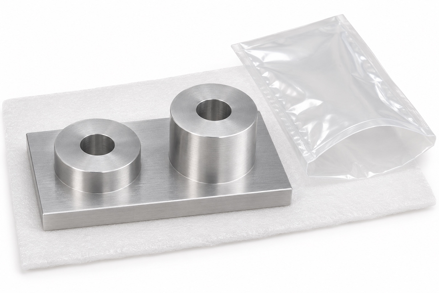
Separate the plate from loose hardware and protect both boss tops, bore entries and the underside against raised marks. Packaging should preserve identification without applying labels to controlled contact surfaces. State any cleaning condition and residue requirement actually included in the order, together with the expected verification. Ordinary protective wrapping does not establish sterility or validated cleaning. Consider how a receiving inspector can identify the taller and shorter feature consistently without adding an unauthorized mark to the part. A controlled drawing orientation or packaging record can provide that link while leaving functional surfaces unchanged.
Prepare a feature-based aluminum machining RFQ
Provide the current drawing, model, quantity, material condition and actual acceptance needs for the two-boss plate. Identify base references, individual heights, any height-difference control, annular contact zones, bore positions and finishing restrictions. Ask for DFM review of stock allowance, access between bosses, setup transfer and final measurement condition. Specify inspection evidence and packaging without inventing a clinical or sensor-performance test for a mechanical fixture part. A focused custom CNC aluminum quotation makes the manufacturing scope comparable between suppliers and keeps the intended interface explicit rather than relying on photographs or a broad claim of medical machining capability.
FAQ
Should both boss tops be coplanar?
Not in this proposed geometry. The bosses intentionally have unequal heights. The drawing should define the required individual heights and any controlled difference instead of treating all mounting seats as a single common plane.
Does a correct height difference prove both heights?
No. Two incorrect absolute heights may still have the specified difference. Review individual dimensions and any direct relationship together, with an explicit base reference and consistent measurement condition.
Can screws passing through the holes release the bores?
No. A clearance observation does not establish bore size, spacing, axis relationships or local wall requirements. Use methods suitable for each characteristic identified by the drawing and record any trial fit separately.
Is one height reading enough for a boss top?
Not if the drawing also controls form or orientation. One point cannot establish a complete annular surface. Define the contact region, point coverage, edge exclusions and evaluation method for the actual requirements.
Does the plate qualify a dialysis pressure sensor?
No. It is discussed as an inert mechanical fixture component. Pressure calibration, electrical safety, fluid compatibility and treatment performance need separate application-specific evidence and are not established by machining conformity.
What information helps a small-batch CNC quotation?
Include drawing revision, model, quantities, 6061 condition, base references, boss heights, height difference if controlled, bore requirements, finishing sequence, inspection condition and packaging. State any separate fixture validation work explicitly.

tanghangyun@oemach.com