
Define the locator without assuming a locating result
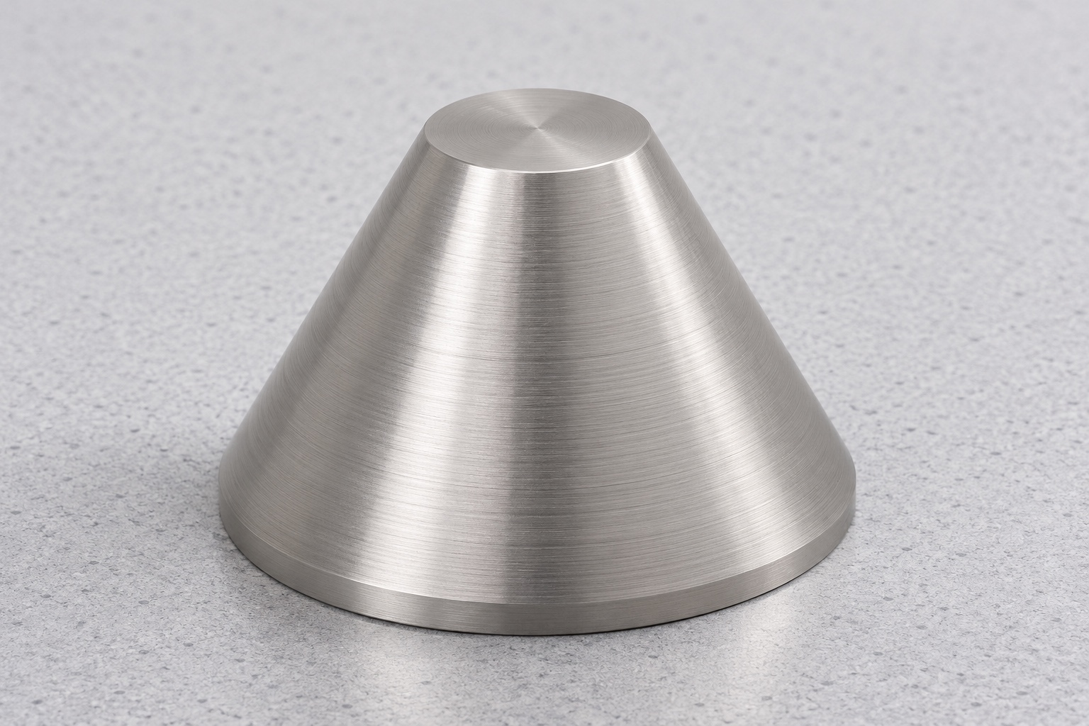
A conical locating piece may provide a geometric contact in a separately designed surgical instrument inspection fixture. The proposed component is a solid truncated cone made from 316L stainless steel: a broad flat circular bottom, a smaller flat circular top and a straight tapered side. It has no bore, thread, projecting flange, shaft or attachment hardware. Small edge treatments must remain outside the defined working region. This guide explains the drawing and CNC turning questions, not an achieved positioning accuracy or a qualified instrument fixture. The designer must still identify the mating shape, support and retention arrangement before the component can be evaluated for its intended task.

Distinguish the half-angle from the included angle
The angle between the cone surface and its axis is not the full included angle seen in an axial section. A drawing should state the convention and the reference direction explicitly. For ideal nominal geometry, the diameter change over the defined axial length describes the taper; dividing the diameter change by twice that length gives the tangent of the half-angle. That nominal relationship does not establish local surface form or finished-part conformity. If end diameters, length and angle all carry tolerances, reconcile their combined requirements. A supplier should not choose one interpretation silently when the drawing permits conflicting acceptance decisions.
Define where a cone diameter is evaluated
A diameter on a tapered surface changes with axial position. Specify the plane or distance from the agreed reference at which a controlled diameter applies. Measurements at two different heights can differ even on a perfectly nominal cone. The small top and broad bottom may also contain edge breaks that must be excluded from the usable taper length. State how those transitions are treated instead of measuring an arbitrary visible boundary. A generic outside-diameter callout without an axial location can therefore be inadequate for a conical locator, particularly where the mating contact uses only part of the tapered surface.
Connect the bottom face and the taper reference
Identify which physical surface establishes axial seating and how the part is supported during inspection. The broad bottom may be a primary reference, but that choice must follow the fixture's intended contact rather than convenience alone. Review the required relationship between that face and the cone axis. A fitted cone can provide an evaluated axis, while the specified datum system determines which relationships matter for acceptance. Circular geometry does not supply an absolute rotational index, and none is added to this plain part. Define support and restraint conditions so that the measurement record describes the actual state being evaluated.
State the 316L material and surface condition
The procurement record should identify the required 316L material, stock form and supporting documentation. Maintain that identification through turning, edge treatment, cleaning and any separately approved finishing process. A bright machined surface is not a material certificate, and a material certificate is not a dimensional inspection report. If passivation or another treatment is required, specify its scope and relevant acceptance evidence rather than inferring it from the alloy name. The proposed fixture context does not establish corrosion performance, sterilization compatibility or patient-contact suitability. Those application questions need their own material, process and exposure information.
Plan turning around the final reference relationship
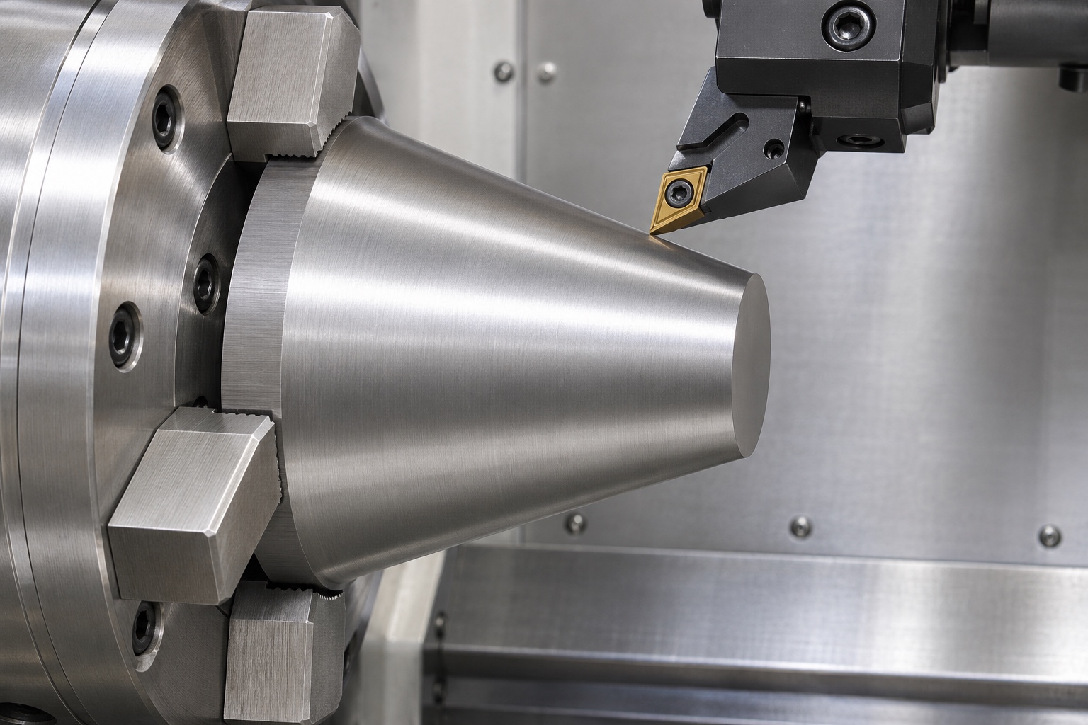
A candidate CNC turning route creates the circular end faces and tapered exterior with sufficient allowance and access for the intended sequence. Review how the blank is held, how the final bottom face is completed and what changes when the part is transferred between setups. Chuck location is a manufacturing choice, not automatically the drawing datum. Tool access and support should preserve the specified usable cone surface without adding an unauthorized holding feature. Process selection depends on actual dimensions, tolerances and available equipment. This guide supplies no universal speed, feed, cycle time or proof that a particular setup has already produced conforming parts.
Protect the usable tapered surface during edge work
Define the small top edge, broad bottom edge and any permitted transition separately from the working tapered band. Removing a burr should not shorten that band or introduce an uncontrolled blend where the mating part is intended to contact. Cosmetic polishing can change local form without being obvious in a general photograph. If surface texture is controlled, identify the relevant area and an appropriate measurement method. A smooth appearance alone cannot establish roughness or the absence of isolated high points. Proposed changes to reliefs, edge breaks or contact boundaries belong in drawing review before they become production details.
Separate angle inspection from contact assessment
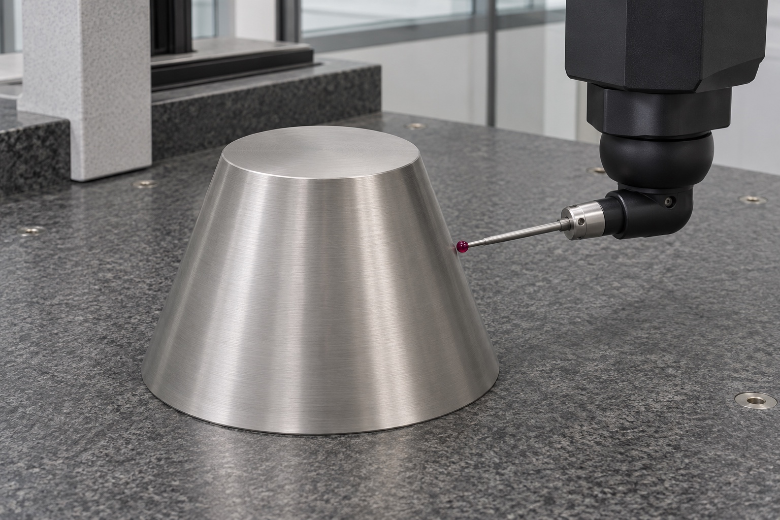
A measurement strategy may evaluate distributed surface points or a suitable axial profile, depending on the drawing characteristics and instrument capability. A single diameter reading cannot establish the taper angle, and an acceptable angle does not prove the entire surface form. State measurement locations, edge exclusions, alignment and evaluation method. If a contact check with a mating reference is requested, define that reference and the limited observation separately. A visible contact mark is not automatically a full surface-form report or a positioning result. The inspection package should make clear which requirements each method actually evaluates.
Link first-article evidence to individual features
Record drawing revision, material identity, manufacturing state and the method for each controlled feature. Relevant entries may include axial length, evaluated diameters at defined planes, angle convention, face relationship, usable taper region and specified surface condition. Use observations from actual parts rather than copying nominal model values into result fields. Where an evaluated axis or derived dimension is reported, identify the underlying measurements and calculation. Resolve uncertainty or access limitations before declaring conformity. A focused first-article plan helps compare requirements with evidence, whereas naming a sophisticated instrument without describing its use does not establish acceptance.
Keep inert fixture observations bounded
An agreed placement in an unpowered inspection fixture may identify interference or a misunderstood contact region. The observation should identify the mating reference, fixture revision and test condition. It does not determine positioning repeatability, holding force, instrument accuracy, wear life or clinical suitability. The mating component and its restraint also influence the outcome, so a satisfactory visual placement cannot be assigned solely to the cone. Treat such information as supplementary to component inspection. Any performance requirement for the assembled fixture needs a separate evaluation designed to measure that requirement, not an inference from the cone's appearance or ease of seating.
Clean and package the contact surfaces deliberately
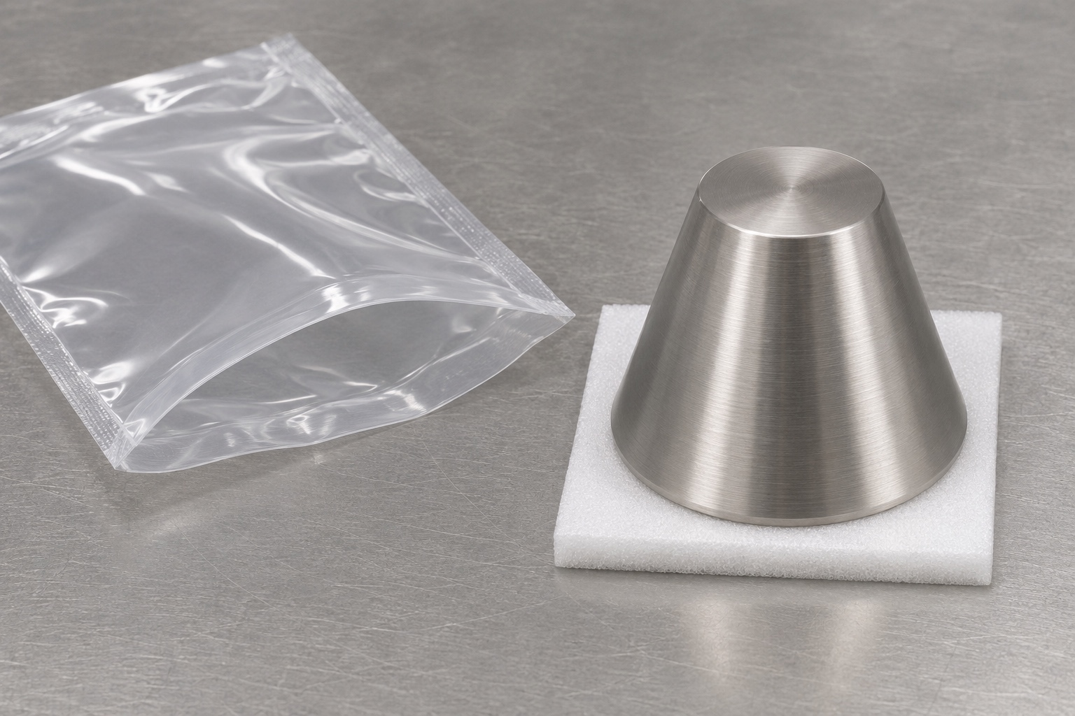
Define the intended outgoing condition and any residue limits actually needed. Cleaning access and handling should protect the tapered band and both end faces from raised marks or loose debris. Keep parts separated so the broad edge of one locator cannot damage another's working surface. Maintain identification through the container or controlled record when direct marking is restricted. A clean protective support and an unprinted pouch do not demonstrate a sterile barrier, validated cleaning or qualified transport. Those claims require separately specified processes and evidence. Preserve the distinction between protective packaging and the dimensional acceptance already performed on the part.
Prepare a complete conical locator RFQ
For a custom 316L CNC turning quotation, provide the current drawing, model, quantities, material requirements and supplied surface state. Include the angle convention, axial reference, diameter evaluation planes, usable contact region and relevant face relationships. Clarify finishing, inspection condition, traceability and protective packaging. Ask for DFM review where workholding, setup transfer or measurement access may affect the requirements. Do not substitute a photograph for the taper definition or ask the supplier to invent a standard fit. Clear inputs support a measurable machining scope while keeping fixture validation and surgical instrument performance with the responsible engineering project.
FAQ
Is the cone half-angle the same as the included angle?
No. The half-angle is measured between the tapered side and axis; the included angle spans both sides in an axial section. The drawing must identify its convention rather than leave the supplier to infer it.
Why specify an axial plane for a diameter?
The diameter changes along the taper. Define the measurement plane or distance from the agreed reference, excluding edge transitions where appropriate. An unspecified height can produce different readings without proving a machining error.
Can one diameter reading verify the complete taper?
No. It does not establish angle, local form, usable contact length or face relationships. Each specified characteristic needs a suitable method with appropriate access, alignment and measurement capability.
Does a 316L material record prove passivation?
No. Alloy identification and a specified surface treatment are separate evidence questions. Define any required treatment and its documentation explicitly; neither visual brightness nor the material name proves that it was performed.
Does an inert seating check prove positioning repeatability?
No. It can support a limited observation of contact or interference. Repeatability, force, wear and system accuracy require separately defined tests of the relevant assembly and conditions.
What should a small-batch quotation include?
Provide the revision-controlled drawing and model, quantities, material, taper convention, reference system, controlled diameter planes, contact region, finishing, inspection and packaging needs. Define any fixture performance evaluation as a separate scope.

tanghangyun@oemach.com