
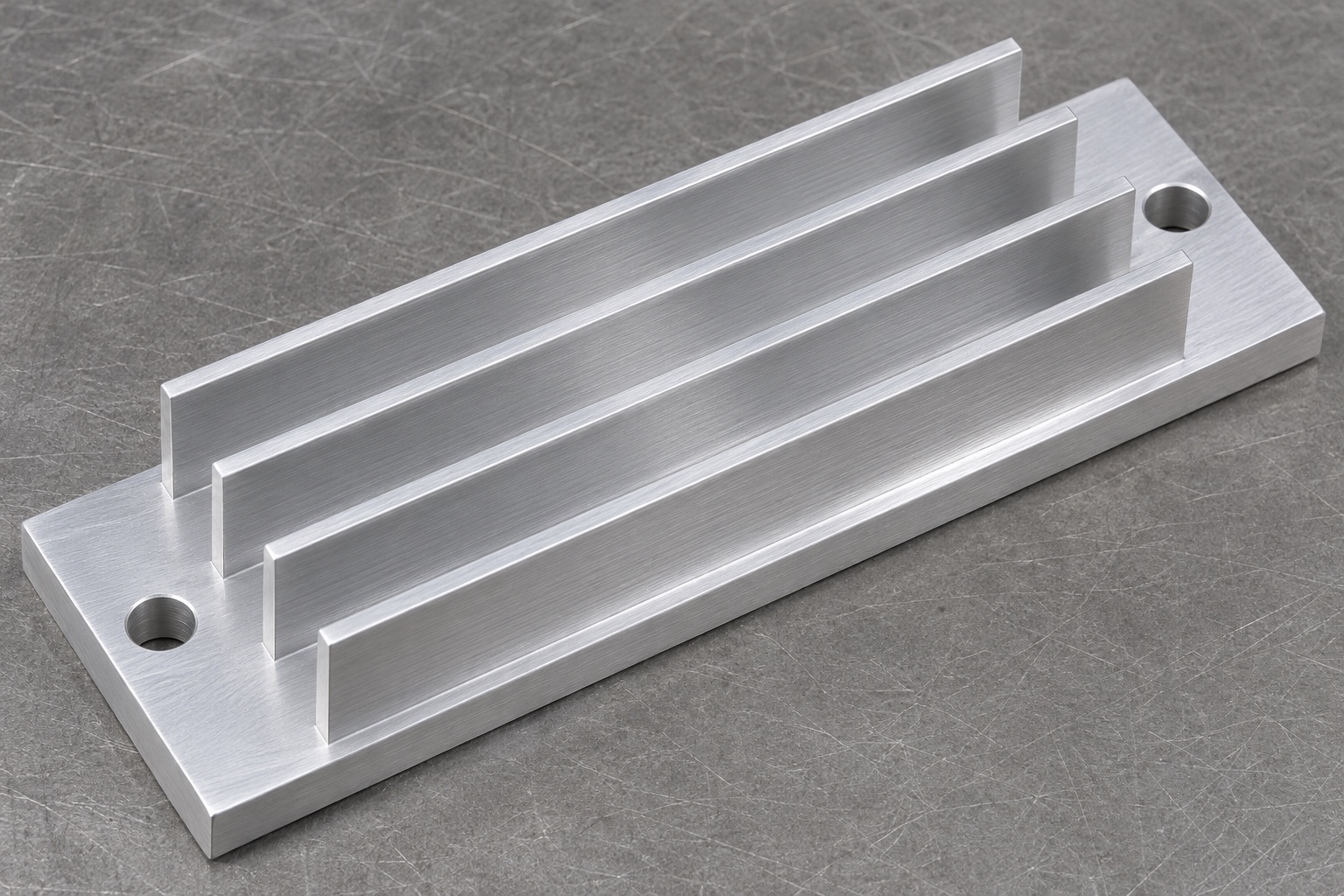
Representative project scope and limits
This representative case proposes a 6061 aluminum LED heat sink block for an unpowered diagnostic photometer fixture study. It is not a record of a customer shipment or an operating medical device project. No measured tolerance, thermal result, optical stability, certification or production capability is claimed. The case follows the questions that would be resolved before a real machining order: contact base, fin channels, mounting references, material condition and inspection access. It separates a proposed fabrication route from the independent qualification of heat transfer and performance within a complete photometer assembly.

Complete proposed component features
The proposed block consists of a rectangular solid base with four straight parallel longitudinal fins forming three open-ended channels. The base extends beyond the fins at both short ends. Each exposed end margin contains one plain vertical mounting through-hole, giving two mounting holes in total. The underside is a flat interface surface. There are no internal coolant passages, tubes, threads, inserted hardware or electronics. This explicit feature list prevents a machining inquiry from gaining unapproved details. Dimensions, edge breaks and permitted transitions would be established by the approved drawing, not scaled from the images.
Define the unpowered assembly interface
The fixture designer would identify the base contact region, mounting references, available clearance and any surfaces that must remain free. An inert interface reference could help review access and gross interference, but it would not establish a thermal contact result. Mounting pressure, interface material and surrounding airflow would remain separate design inputs. If a hole is intended only for fastener clearance, its role should not be confused with precision location. The proposed route starts from these functional distinctions so that tolerances and inspection effort are assigned to the correct surfaces and relationships.
Drawing package and quotation assumptions
A real RFQ would include the drawing revision, model, quantities, required 6061 alloy condition, final treatment and inspection scope. Highlight base flatness and texture where functional, fin thickness and channel dimensions, hole positions and any datum relationships. State whether measurements apply before or after treatment and whether the part is inspected free or under a defined restraint. Any unprovided tolerance or treatment remains an open item rather than an assumed workshop standard. The quotation should identify DFM exceptions explicitly, especially where tool reach or probe clearance conflicts with a requested feature.
Material identity and proposed blank preparation
Identified 6061 stock would be selected in the specified condition and associated with the required documentation. Blank preparation would reserve material for the base, fins, workholding and finishing sequence without assuming that a visibly flat stock face is the final contact surface. Traceability would remain with the workpiece through machining and any approved external treatment. The alloy name does not prove the finished component's thermal behavior or corrosion resistance. This example supplies no material certificate or treatment report; it explains which material and process records a real order would need to define and retain.
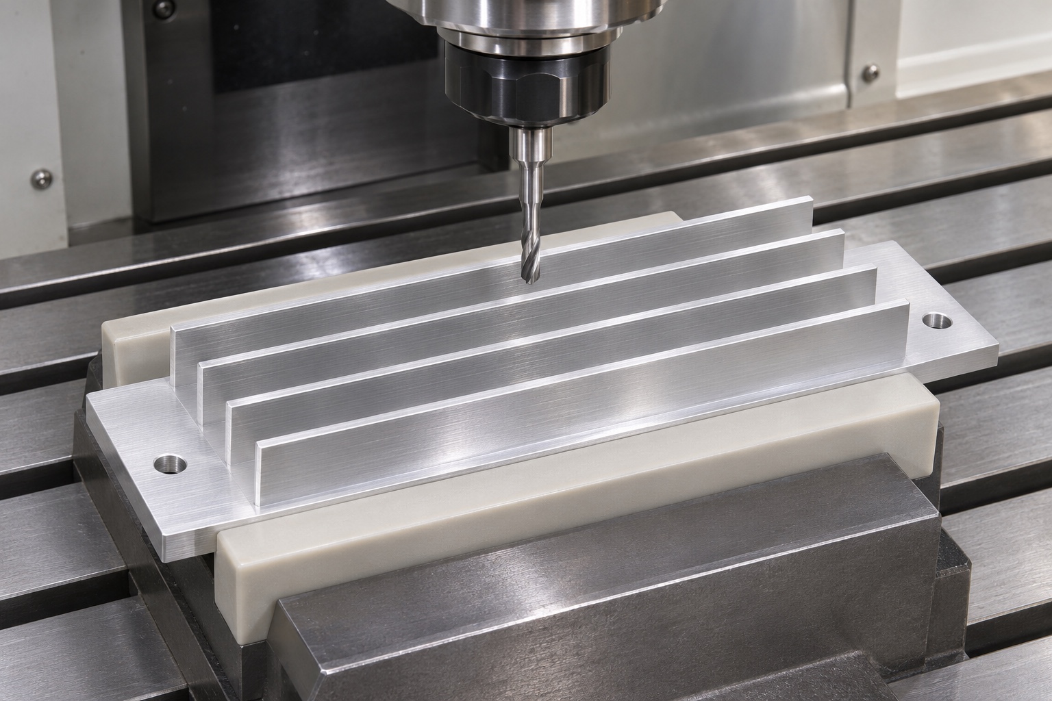
Proposed base support and cutter access
The proposed setup would grip and support the solid base while allowing the cutter to reach the channels and end margins. Slender fin tips would not be treated as ordinary clamping pads. Review cutter diameter, reach, holder clearance and the changing support as material is removed. Open ends help access but do not guarantee a stable cut. If an alternative fixture or geometry is proposed, it would require review against the approved drawing. A setup image communicates a possible arrangement, not proof that a finished block was machined with a particular accuracy or cycle time.
Proposed roughing and finishing sequence
The plan would coordinate channel roughing, fin finishing, base surfaces and mounting-hole operations so that later work does not damage earlier finished features. The actual sequence would depend on dimensions, stock condition, tooling and workholding. No universal pass depth, speed, feed or finishing allowance is asserted. Any intermediate operation affecting final shape would be documented. The route would also preserve inspection access for narrow spaces between fins. A machining simulation or plausible tool position would support planning, but neither would replace first-article evidence from actual components made to the released drawing.
Channel exits and mounting-edge control
After milling and drilling, both channel exits and both sides of the mounting holes would need review for burrs and permitted edge condition. The base contact surface would be protected during this work. Edge removal would not be used to hide a narrow channel, thin a fin or alter an unapproved radius. If a required edge cannot be reached with the proposed method, the issue would be resolved before accepting the part. An attractive top surface would not establish the condition of the underside, channel corners or hole exits, which may require separate views or methods.
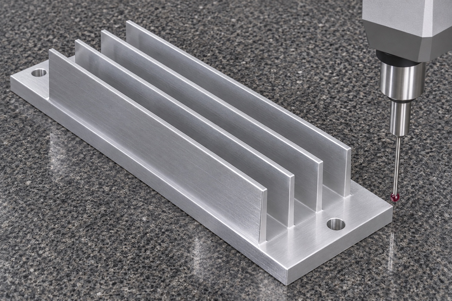
Proposed first-article inspection package
The inspection record would identify the part, revision, material, final state, datum alignment and actual results. It would assign suitable methods to base size and flatness, fin height and thickness, channel width, mounting holes and required relationships. Probe access and contact force would be reviewed to avoid interpreting fin deflection as component geometry. An optical view could supplement but not automatically replace contact or underside checks. Instrument photographs are not dimensional reports, and CAD nominal values are not measured results. Features outside a method's reach would be declared before a release decision.
Supplementary assembly observation without thermal claims
An approved unpowered reference could support an observation of mounting access, base seating and clearance around the fins. That observation would identify the reference and the assembly condition. It would not demonstrate heat dissipation, LED temperature, electrical isolation, optical measurement accuracy or performance in an enclosed operating instrument. If a later design requires powered testing, the responsible team would define the heat source, interface, mounting, airflow and test conditions separately. The proposed machining scope remains useful because it states precisely which geometric evidence could be provided without claiming system performance that was not evaluated.
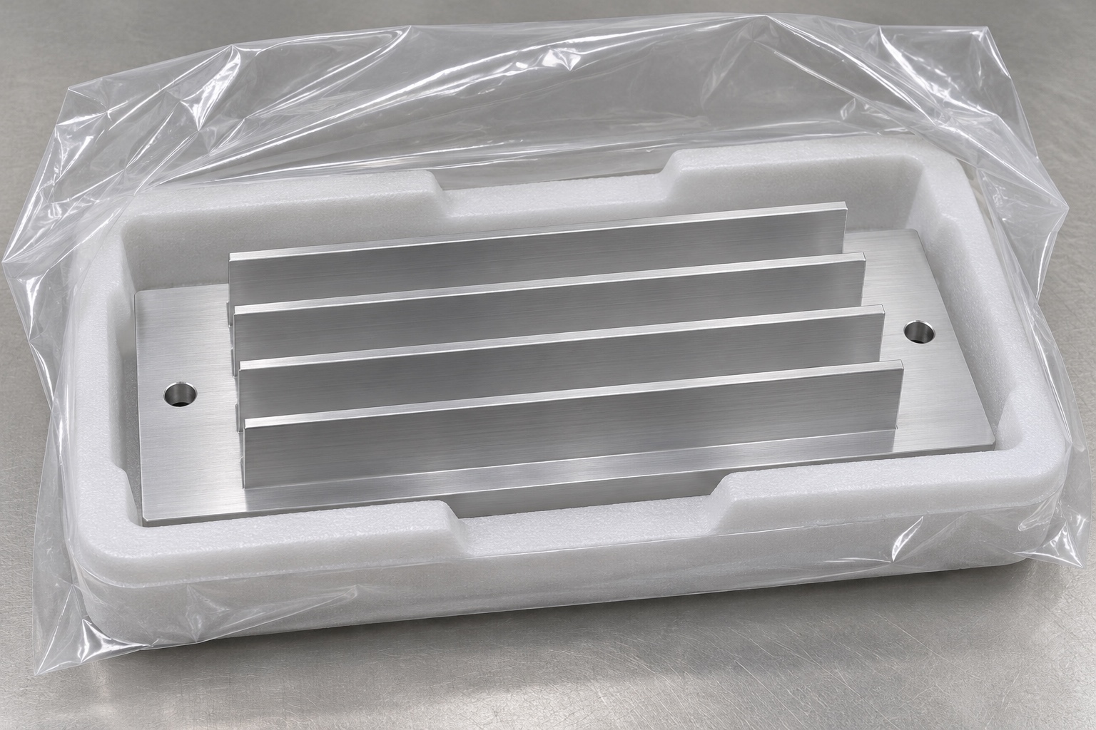
Outgoing cleaning and protective packaging
The proposed outgoing condition would include removal of machining debris according to the agreed requirements, with particular attention to channels and hole exits. Any residue or particle limit would need its own verification method. Packaging would support the base and keep fin tips from carrying stacking loads or contacting neighboring components. Identification would remain outside the functional contact surface. The pictured protective arrangement is not a sterile package or a validated shipping test. This case reports no shipment or cleanliness result; it describes the handling questions to settle before actual components are transferred to a receiving team.
Approval path for a real aluminum small batch
Before production, the parties would approve the drawing, model, alloy condition, quantities, treatment, inspection methods and packaging. DFM items would include channel cutter reach, base support, edge access, probe clearance and the final measurement state. A real first article would then provide the agreed evidence for the manufactured part, with changes recorded before repeat orders. Thermal and optical qualification would remain separate from dimensional release. This proposed case supports a focused inquiry for custom medical aluminum parts without inventing a customer delivery, production result or validated photometer performance.
FAQ
Is this heat sink a documented customer delivery?
No. It is a representative CNC milling example for an unpowered fixture study. No shipment, measured compliance, certification, thermal performance or actual photometer validation is asserted.
How many fins and mounting holes are proposed?
The proposed block has four longitudinal fins, three open-ended channels and two plain mounting holes, one in each exposed end margin. It contains no coolant passages, tubes, threads or electronics.
Why does the proposal support the base instead of the fin tips?
The solid base offers a different workholding opportunity from slender fins. The actual setup must resist cutting loads without unacceptable distortion or damage and preserve the specified final condition.
What does the proposed first-article report cover?
It would record the actual features, methods, alignment, final state and results agreed for real parts. It would not turn a gauge photograph or nominal model dimensions into measured compliance.
Does 6061 alone specify the supplied material completely?
No. The inquiry should identify the required alloy condition, stock form and documentation, plus any final treatment and measurement state. Thermal performance requires separate evaluation of the assembled design.
What remains outside the machining acceptance scope?
Powered thermal behavior, LED temperature, optical accuracy, electrical safety and operating-device qualification remain separate unless explicitly defined and supported by appropriate additional testing and evidence.

tanghangyun@oemach.com