
Representative cap project without a delivery claim
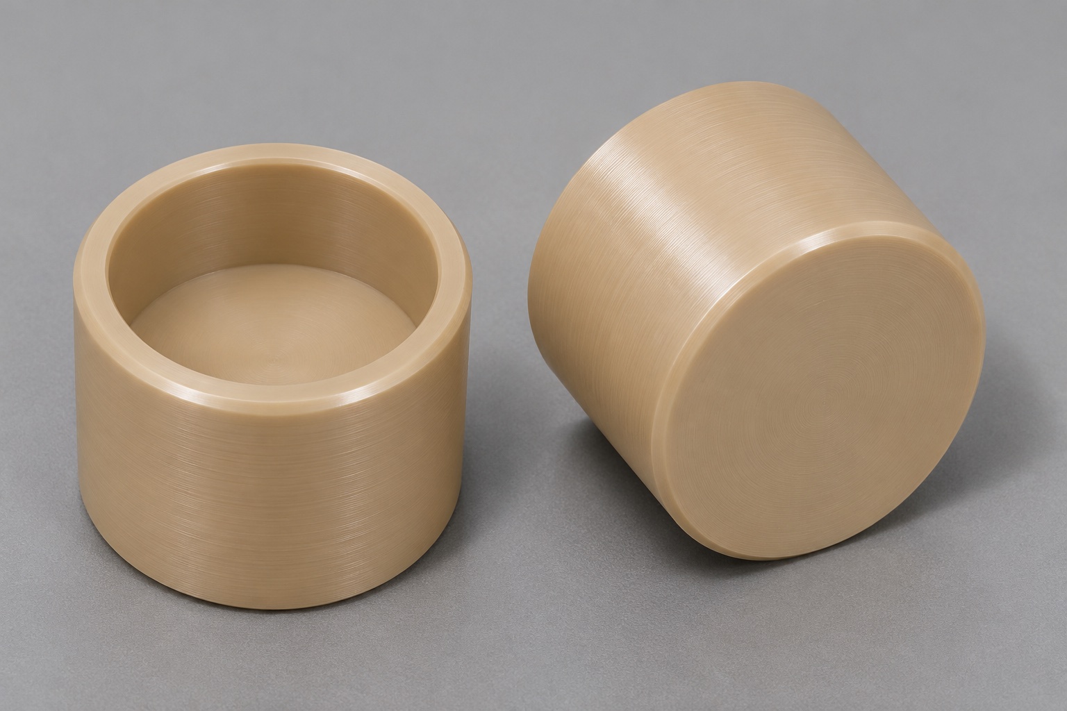
This case proposes a natural unfilled PEEK cap for an inert analyzer-probe transport-fixture study. It is a representative CNC turning example, not a documented customer order or completed shipment. No actual probe compatibility, transport protection, sterility, certification or measured production outcome is asserted. The purpose is to connect a closed-end polymer geometry with the drawing, machining and inspection decisions needed before a real order. The complete transport arrangement and any analytical instrument interfaces remain separate design responsibilities. A cap that surrounds one dummy envelope in a photograph has not thereby demonstrated tip protection, retention, contamination control or performance during actual shipping and handling.

Visible geometry and excluded features
The part is a short plain cylinder with one smooth blind axial recess and an integral flat closed bottom. The recess is accessible from the mouth, with the floor and wall transition defined by the approved drawing. Small edge treatments do not imply a separate flange or retention feature. There are no through-holes, vents, threads, grooves or inserts. The mouth, internal wall, floor and outside cylinder are separate manufacturing features. Images communicate their general arrangement, not production dimensions. An actual component must follow the released drawing and model rather than a guessed diameter, depth or bottom section derived from the appearance of a representative product scene.
Probe-envelope and contact definition
The real design review should identify the inert reference that enters the cap, its permitted depth and areas that must remain clear. Decide whether any surface locates or stops the reference or whether the cap simply surrounds it with specified clearance. Unexpected bottom contact can arise from either reference or component geometry, so both definitions must be controlled. This example does not assume a fluid seal, a friction retention force or impact protection. If the real transport system requires those functions, define and qualify them separately. The manufacturer's bounded role is to produce and evaluate the approved cap geometry, not infer complete system performance from an apparently comfortable fit.
RFQ and material-control requirements
Provide the released drawing and model, unfilled PEEK definition, stock form and condition, quantities and required records. A filled PEEK grade or another visually similar polymer is not an automatic substitute. Highlight the internal envelope, mouth condition, recess depth reference and any required remaining-bottom section. Identify inspection state, cleaning and packaging expectations before quotation. Ask the supplier to disclose gripping, tool-access and measurement limitations. A meaningful price should compare the same material, geometry and evidence scope across suppliers. The general reputation of PEEK does not replace a grade-specific definition or support an unrequested regulatory, cleanliness or transport-performance claim for the finished cap.
Stock preparation and proposed clamping
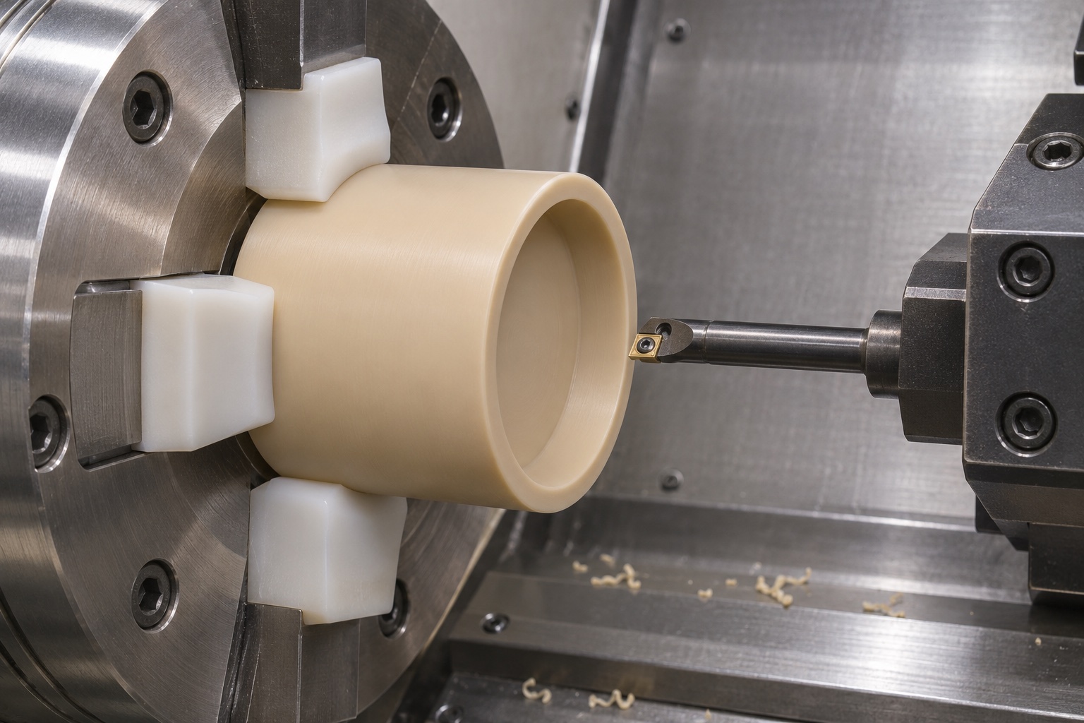
Keep blanks associated with stock identity and drawing revision throughout the route. The proposed workholding should resist cutting forces without unacceptable distortion or marks on functional surfaces. Review grip length and the changing section as material is removed from the recess. If shaped jaws or a dedicated support are selected, record their relevant geometry and condition. Do not assume a solid-metal turning setup is suitable without review merely because the PEEK blank is also cylindrical. Actual clamping conditions and process decisions must be verified for the real dimensions and requirements. No universal grip force, cutting recipe or guaranteed dimensional stability is asserted in this representative planning case.
Proposed blind-recess machining route
The manufacturing engineer should select a sequence for facing, outside turning and producing the blind recess while preserving recoverable references. Review the tools needed for the wall, floor and internal transition. A preliminary drilled opening must not leave an unapproved conical bottom or remove material beyond the specified depth. The boring tool needs adequate access and clearance at the mouth. There is intentionally no vent or exit opening in the bottom; adding one for chip removal changes the geometry. The machining image illustrates a possible tool arrangement, not evidence that a real part has achieved a particular depth, profile tolerance or production capability.
Chip removal and final part condition
The closed recess requires a considered chip-evacuation approach instead of relying on a through-hole exit. Review tool condition, cooling and removal of retained debris for the actual operation. Define how the component moves from machining to acceptance measurement, including the required environment and any specified stabilization. Do not equate a warm, tightly clamped reading with the released condition required by the drawing. The case does not prescribe a universal waiting time or treatment. If an intermediate operation or alternate stock preparation is proposed, obtain approval and preserve the record so later measurements can be interpreted against the manufacturing condition actually used.
Mouth, floor and bottom-section requirements
The drawing must distinguish mouth edge treatment, internal depth, floor condition and remaining bottom material. A depth measurement alone does not establish every one of those features. Review the method needed for a minimum-bottom requirement rather than inferring it from a nominal overall height. Do not deepen the recess or enlarge an entry chamfer simply because a dummy appears difficult to insert. First identify the cause and compare the approved interfaces. Internal transitions should follow the drawing instead of a convenient tool-tip radius. Deburring must remove unacceptable fragments while preserving the specified wall, mouth and floor geometry and leaving relevant areas accessible for assessment.
Proposed first-article inspection package
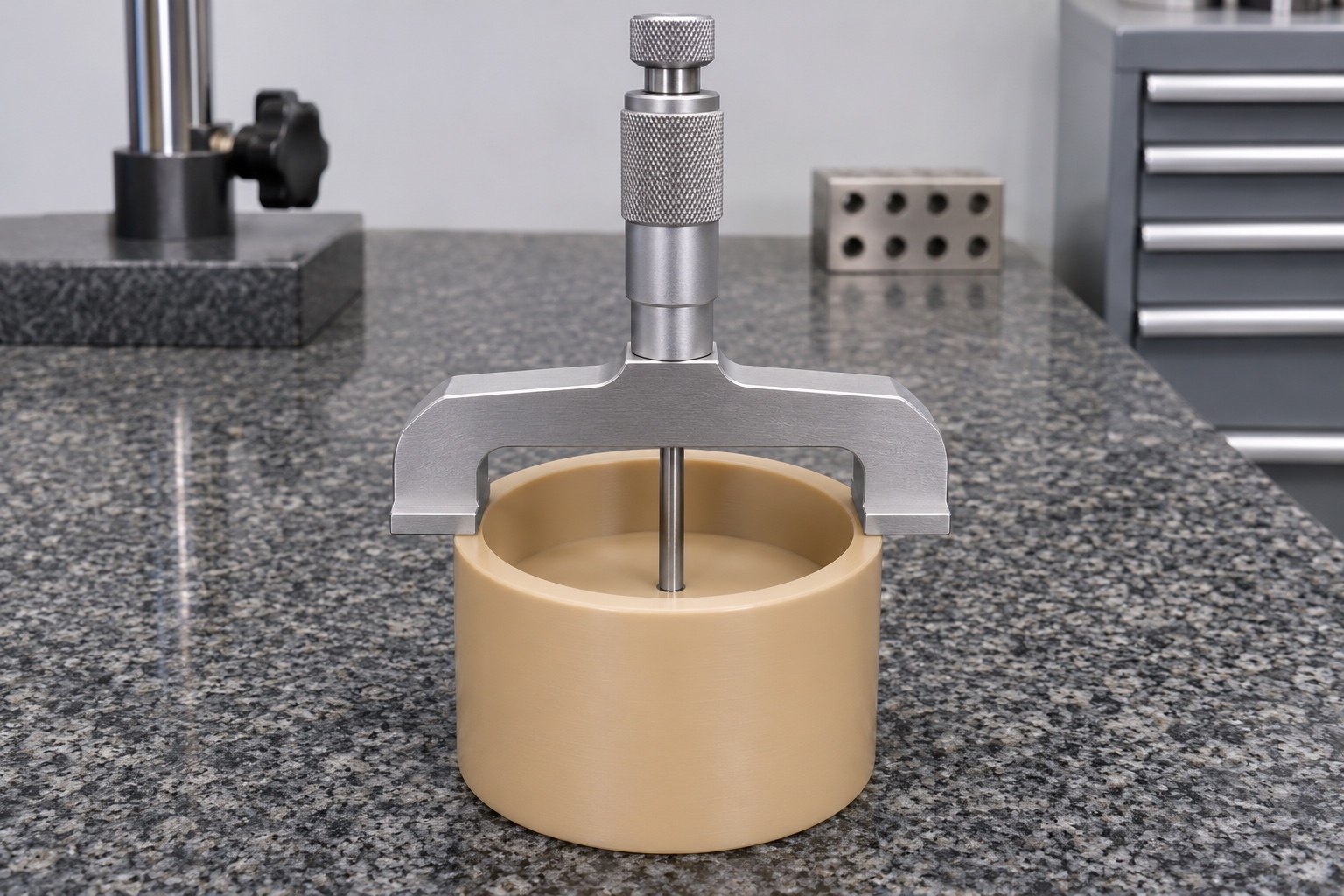
An actual report should identify component and revision, material, measurement state, references and real readings. Assign outside size, overall height, internal diameter, recess depth, mouth and floor requirements to appropriate methods. The illustrated depth instrument shows a possible contact arrangement; it does not prove remaining bottom thickness, bore diameter or complete internal profile. Agree support and measuring force for the polymer part. If a feature cannot be assessed credibly with the available equipment, disclose that limitation before acceptance. The case contains no fabricated measurement data or passing certificate. CAD nominal values, an inserted dummy and a gauge photograph cannot replace the required dimensional evidence.
Supplementary inert insertion observation
If requested, an approved dummy probe envelope can show gross access, visible interference and insertion behavior under a defined condition. Record its revision and the observation procedure. Do not use real analytical probes, biological material or a working analyzer as an improvised experiment. Hand placement cannot establish protection against impact, retention during shipping or preservation of cleanliness. If the reference touches the floor unexpectedly, review its dimensions and the cap before modifying either. The responsible design owner should decide the necessary revision. The supplementary observation helps identify an engineering question; it should not silently redefine the component's dimensional acceptance or qualify the complete transport system.
Internal cleaning and protective package design
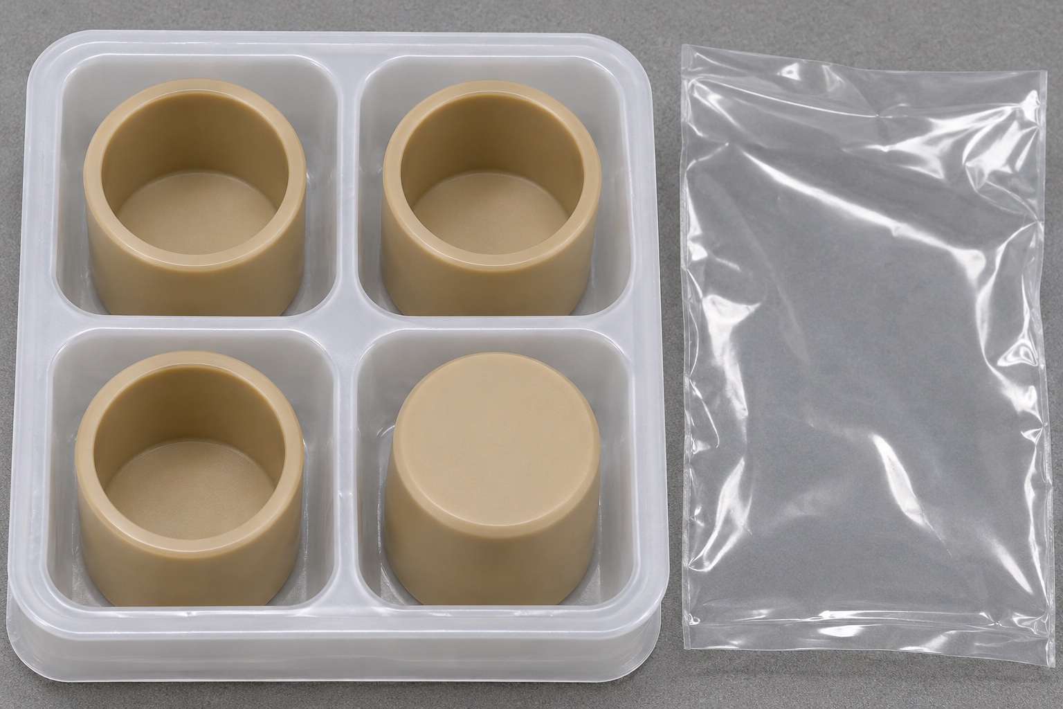
The real order should define permitted cleaning agents, drying and outgoing handling for the actual PEEK grade and recess. Remove loose chips from the closed cavity and specify how its condition is assessed. Ordinary cleaning does not establish a numerical residue limit or sterility. Keep packaging from introducing fibers, abrasive material or pressure damage at the mouth. Separate caps where mutual contact could compromise the required delivery condition. Link package identity to part number, revision and the required material and inspection records. The representative tray and clear bag illustrate ordinary protection, not a completed shipment, sterile barrier or validated method for preserving an actual analyzer probe.
Release path for a real custom cap order
Before manufacture, approve the drawing, model, material, quantities, inner envelope, depth and bottom requirements, inspection plan and handover condition. Resolve supplier exceptions and distinguish any dummy observation from transport qualification. Preserve accepted setups, inspection references and actual first-article results for repeat manufacture, documenting changes rather than copying nominal values into new reports. This representative case makes no promise about delivery outcome, achieved capability or instrument protection. It structures a request for precision polymer fixture parts around measurable features and responsibilities, keeping component turning evidence separate from the design owner's evaluation of a complete probe transport arrangement and its real operating or shipping conditions.
FAQ
Is this an actual analyzer customer delivery?
No. It is a representative CNC turning example without an asserted shipment, customer identity, measured production result, certification or real-probe protection outcome.
What makes the cap a blind-recess part?
Its axial opening ends at an integral closed floor. There are no bottom vents, through-holes, threads, grooves, flanges or inserts in the proposed geometry.
Does a depth gauge verify all internal requirements?
No. Define the scope of the measurement. Internal diameter, floor condition, remaining bottom material and specified geometric relationships may require separate methods.
Can a filled PEEK grade be used automatically?
No. The example specifies unfilled PEEK. Any material change needs application-specific review and approval before it changes the controlled manufacturing definition.
Does dummy insertion validate shipping protection?
No. It is a bounded inert geometric observation. Actual impact, retention, cleanliness and probe compatibility require separate approved requirements and evidence.
What must be approved before a real order?
Drawing, model, PEEK definition, quantity, inner envelope, mouth and bottom requirements, inspection state, documentation, cleaning, packaging and any proposed manufacturing exceptions.

tanghangyun@oemach.com