
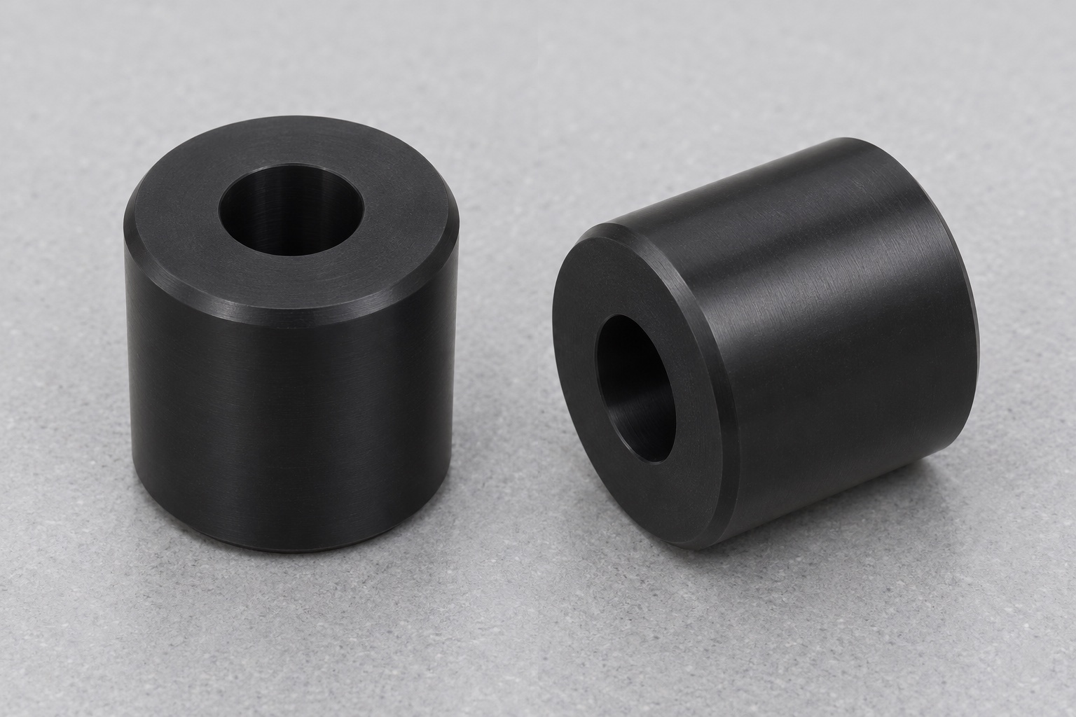
Representative scope without a claimed customer outcome
This case considers a custom black POM-C roller for an inert diagnostic-cartridge transfer fixture. It is a representative machining example rather than a record of a customer project or completed shipment. No achieved tolerance, yield, service life, certification or analyzer performance is claimed. The aim is to connect the component's plain geometry with the decisions needed for quotation, manufacture and acceptance. The real transfer mechanism, cartridge interfaces and operating conditions would require separate design approval and qualification. A roller's simple appearance does not make those responsibilities disappear, and a hand-moved dummy cannot establish the reliability or diagnostic performance of an operational instrument.

Feature inventory and proposed interfaces
The representative part is a short uniform cylindrical roller with flat annular ends and one centered plain axial through-bore. The external and bore-entry rims have small drawing-controlled edge treatments. There are no flanges, grooves, bearings, inserts or threads. The outer cylinder provides the proposed dummy-cartridge contact; the bore interfaces with an approved inert axle reference; the ends face neighboring supports. Each interface needs a defined role in an actual assembly. The pictures communicate material appearance and visible features, not production dimensions. A real order must use the controlled drawing and matching model rather than deriving an outside diameter, bore fit or support clearance from the proportions of an image.
Functional questions to resolve before machining
The design review should identify how the roller is supported, how axial movement is controlled and what relationship is required between the bore and outer cylinder. A plain through-bore does not include a retention mechanism. If the fixture needs additional hardware, define it separately instead of assuming it is concealed inside the roller. Identify the cartridge envelope and whether the outside surface has a specific contact or finish requirement. These questions establish the actual manufacturing scope. They should not be replaced by a generic instruction that the part should rotate freely, because free movement on one dummy axle cannot establish all dimensional and geometric requirements.
Material and RFQ definition for black acetal
Specify POM-C acetal copolymer, color, grade or approved material definition, stock form and the records required with the order. Do not assume that another acetal family or a visually similar black plastic is an automatic substitute. Include the released drawing and model, quantities, outgoing condition and documentation expectations. Highlight the bore role, cylinder requirements, end clearance and inspection state. Where chemical or cleanliness requirements apply, define the corresponding evidence rather than relying on a general material description. A meaningful quotation should disclose substitutions, workholding assumptions and measurement limitations before manufacture, allowing the purchaser to compare equivalent scopes for low-volume precision plastic CNC parts.
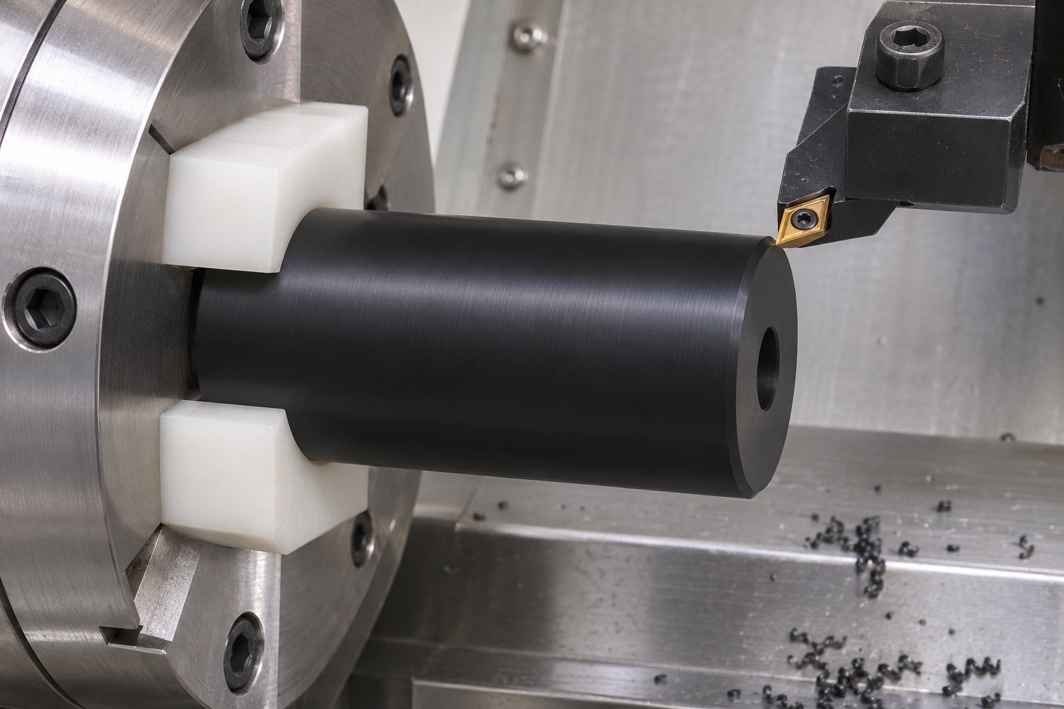
Blank handling and proposed workholding route
Keep cut blanks associated with their stock identity and drawing revision. The proposed workholding must resist machining forces while avoiding unacceptable deformation or marks on the finished cylinder. Review gripping length, support contact and the amount of material that will be removed in each operation. A process appropriate for a metal roller should not be transferred unchanged without considering the plastic component. If shaped jaws or a dedicated support are proposed, identify their relevant geometry and condition. The case does not prescribe a universal clamp force: the actual process engineer must select and verify a suitable arrangement for the stock, dimensions and released drawing requirements.
Turning the cylinder and producing the plain bore
A proposed route establishes an end reference, turns the outside and produces the axial opening with tools appropriate to the actual requirements. The relationship between the outer cylinder and bore should be considered when sequencing these operations. A common setup can support that objective, but it is not evidence that every required relationship has been achieved. Review chip removal, hole finishing access and the reference used for the reverse operation. The entire bore must be evaluated as required, not merely the convenient entrance. This representative case deliberately avoids invented feeds, speeds or process capability figures because those need a real stock, machine, tool selection and component evaluation.
Finishing the second end and controlling part condition
The reverse setup completes overall length and the second end while preserving the intended references. Protect completed surfaces and avoid an unapproved constraint that affects the apparent dimensions. Define how the component moves from machining to final measurement, including the required environment, support and any specified stabilization condition. Do not measure an arbitrarily warm, tightly clamped roller and treat the result as equivalent to the required released-state inspection. No universal cooling interval is asserted here. If an intermediate treatment or alternative stock preparation is proposed, obtain approval before use and record the change so later measurements can be interpreted against the correct manufacturing condition.
Edge cleanup and full bore access
Inspect the outer rims, both bore entrances and the accessible internal surface after loose chips are removed. Remove unacceptable slivers and attached burrs without enlarging the bore or changing the functional cylinder length beyond the drawing. If a dummy axle catches, identify whether the cause is entry damage, size, form or alignment before altering the part. Manual polishing to make one reference fit is not an approved substitute for dimensional inspection. The deburring and visual inspection plan should explain how limited-access areas are addressed. A clean outside appearance is not evidence that the axial opening is free from retained debris or that every internal edge has been evaluated.
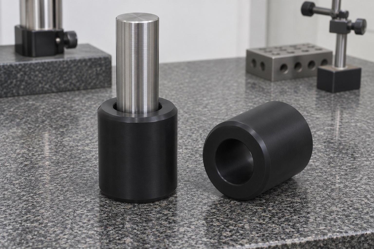
First-article inspection evidence proposed for review
The inspection report should identify part and revision, material, measurement condition and actual readings. Map outside diameter, bore size, length, end condition and specified surface relationships to suitable methods. Review support and contact force for the plastic part, and take the measurements needed to evaluate the requirement rather than recording one convenient location. A plug in the bore illustrates access or a possible supplementary check; it does not provide a measured result or automatically establish bore form. Any runout or relationship observation also requires a defined mounting reference. Disclose equipment limitations before acceptance instead of presenting a generic list of instruments as proof of complete inspection.
Inert transfer observation and its limits
An approved dummy axle and cartridge envelope may supplement the dimensional report by showing gross obstruction, visible end rubbing or assembly access. Record reference revisions and the observation condition. Do not infer operating speed, cartridge protection, transport accuracy or service life from manual movement. The actual mechanism may have requirements that this simple fixture does not reproduce. If movement is inconsistent, compare the measured interfaces and alignment before changing length, opening the bore or adding lubricant. Any lubrication or surface modification must be reviewed for the real application. The purpose of the supplementary observation is to reveal an engineering question, not to silently redefine component acceptance.
Cleaning, separation and protective packaging
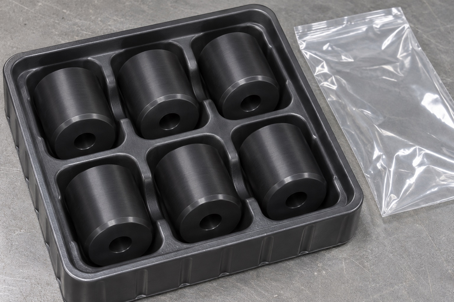
Agree cleaning agents, drying and outgoing handling requirements before shipment. Remove loose debris from the axial opening and protect the outside contact cylinder from abrasion. Separate finished rollers in suitable compartments where rubbing or mixed-part handling could affect their specified condition. Packaging should not impose an unacceptable preload or leave loose material inside the bore. Identify packages with part and revision information linked to the required manufacturing records. A clear protective bag is ordinary manufacturing protection, not evidence of a sterile barrier or validated chemical compatibility. Receiving inspection must follow the actual purchase specification and required records rather than relying on the representative packaging photograph.
Release path for a real custom roller order
An actual order requires approval of the drawing, matching model, POM-C definition, quantities, process exceptions, inspection methods and delivery condition. Define any requested dummy movement observation separately from dimensional acceptance. Preserve approved workholding and inspection revisions with actual first-article results so repeat manufacture can be assessed consistently. This case makes no promise of a particular delivery outcome or analyzer performance. It shows how a low-volume medical analyzer fixture part can be purchased as a bounded manufacturing task. Clear responsibility for the roller's interfaces and evidence supports both the supplier's work and the design owner's separate qualification of the complete cartridge transfer mechanism.
FAQ
Is this roller a documented customer shipment?
No. The case is a representative CNC turning example and does not assert a completed delivery, actual customer, production results or certification.
Does the part include bearings or retention grooves?
No. It is a plain POM-C cylinder with a through-bore and small edge treatments. Any bearings, flanges, grooves or retention hardware need a separate approved definition.
Why specify POM-C rather than only black plastic?
Color does not establish material identity. Control the required acetal family, grade, stock condition and records, and approve any proposed substitution before manufacture.
Can a plug gauge alone establish every bore requirement?
No. Its meaning depends on the gauge and defined procedure. Bore size, form and relationships must be evaluated by methods appropriate to the complete drawing requirements.
What does the dummy transfer observation establish?
Only the documented observation under its defined inert conditions, such as visible obstruction or access. It does not establish analyzer reliability, service life or diagnostic performance.
What starts an actual manufacturing order?
Approve the drawing, model, material, quantities, bore and cylinder definitions, inspection state, documentation, cleaning, packaging and any supplier exceptions or supplementary checks.

tanghangyun@oemach.com