
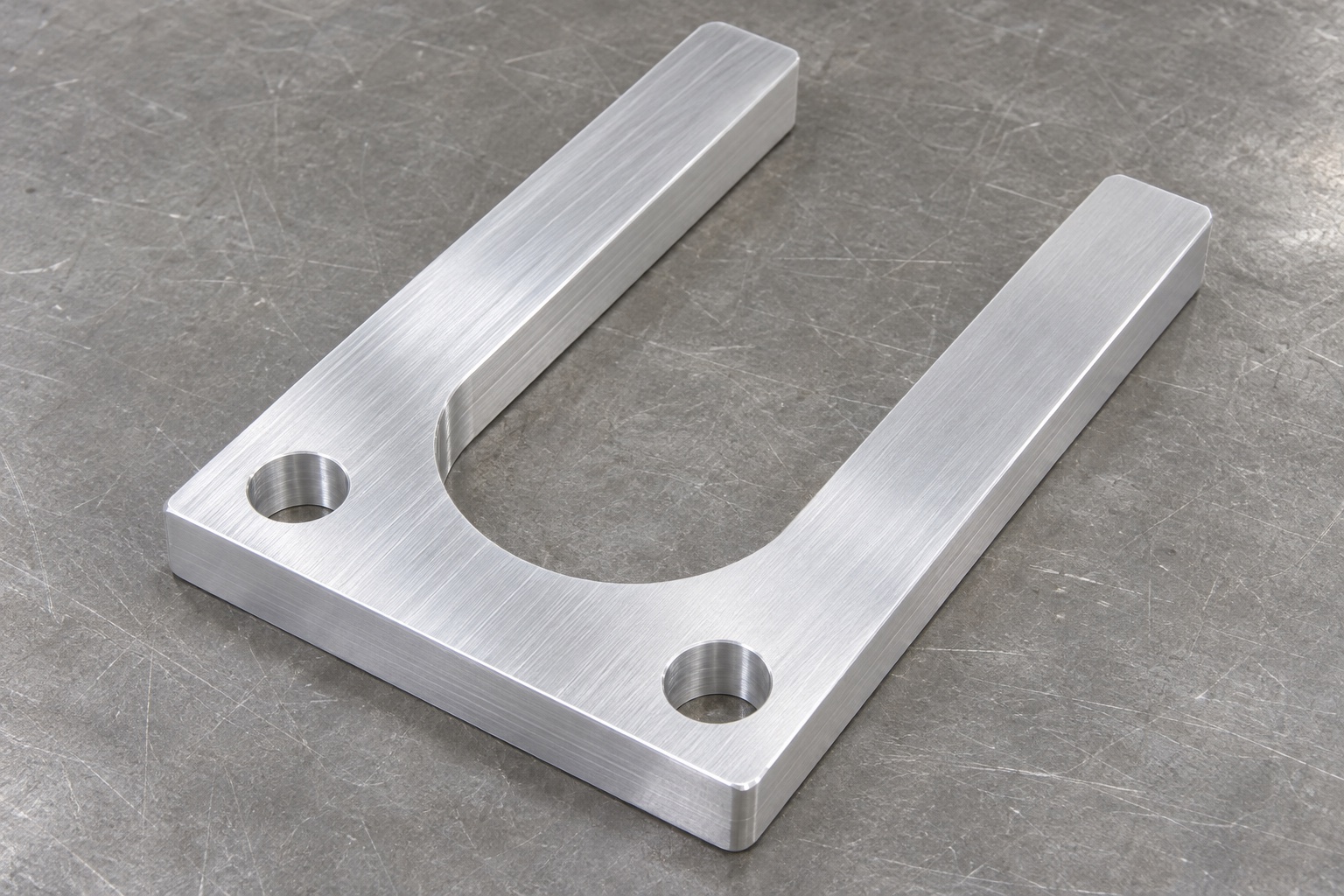
Representative scope of the U-profile support
This case describes a representative 6061 aluminum support fork for an inert audiometer headset bench fixture. It is not a customer delivery report and claims no acoustic calibration, clinical approval or achieved manufacturing result. The proposed part is a thick flat U-profile with two straight prongs and a connecting base. Its central opening has a rounded root, and the base contains exactly two plain mounting through-holes. The part is machined from stock rather than bent from sheet. An identified dummy assembly would be used without powered equipment or a person. Real dimensions, tolerances and acceptance conditions would have to come from an approved project drawing.

Review the reference assembly before assigning tolerances
The proposed design review would request the dummy headset envelope, intended contact surfaces and insertion direction. The assembly owner would define whether the prongs locate a feature or provide clearance and support. The supplier would not infer these relationships from a generic product photograph. A matching CAD model would help review access, while the drawing would remain responsible for dimensional and geometric requirements. If the reference assembly changed, the team would review the fork revision before reusing the old program. This keeps a custom support-fixture quotation focused on the actual mechanical interface rather than an unsupported promise of compatibility with every audiometer headset.
Link 6061 stock identity with the drawing revision
The hypothetical order would identify the required aluminum designation and temper, stock form and material documents. The supplier would confirm the availability of that evidence before accepting real manufacturing work. This example does not assert that a certificate has already been obtained. Cut blanks would remain linked to the traveler through preparation, milling and inspection. A substitution would be reviewed before cutting if it changed an approved requirement or process assumption. The packaged part would carry the same revision identity as the actual inspection report, allowing receiving staff to distinguish similar U-shaped components that belong to different dummy assemblies or mounting arrangements.
Set mounting and contact references as one scheme
The proposed drawing would define the seating face, orientation and origin used for the mounting holes and prong contacts. The two base holes would not be treated as sufficient evidence of the entire support relationship. Hole diameter, pattern location and open-profile position would remain separate requirements. If the fasteners only clamp the fork, that role would be made clear rather than turning a clearance hole into an implied locating fit. The inspection plan would reproduce the approved reference scheme without squeezing the prongs against a gauge. This avoids an apparently correct mounting pattern that nevertheless places the dummy assembly differently from the intended fixture definition.
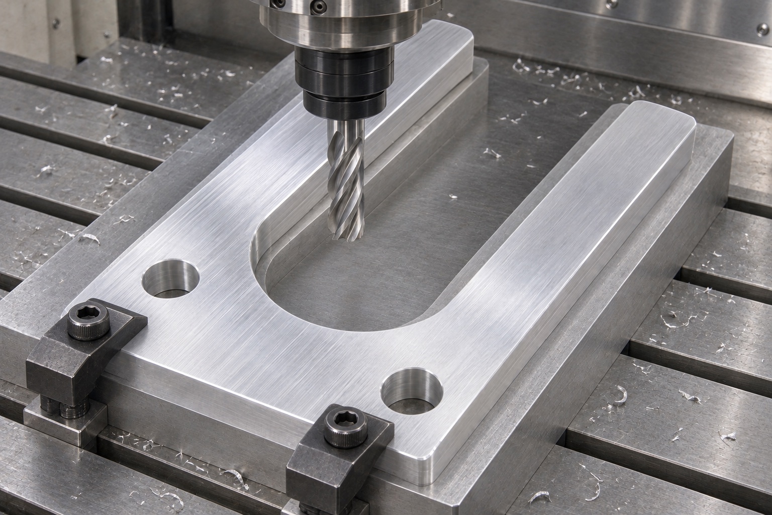
Plan roughing around the opening and prong support
The proposed milling route would consider how support changes as the U-opening and external contour are generated. Suitable finishing stock would remain on the functional faces where required by the plan. Clamping would avoid unsupported tips and keep cutter access clear. A support fixture could be used, with its contact areas and exit paths checked before cutting. No universal speed, feed or cycle time is claimed here. The actual route would follow the real proportions, tooling and machine condition. Its setup would be documented so a repeated small batch did not rely on an operator reconstructing the original prong-support arrangement from memory.
Generate the rounded root and useful straight faces
The finishing operation would follow the approved straight prong faces and rounded root profile. Tool diameter and reach would be checked against the intended transition, not merely against the entrance width. If a relief or different internal radius were necessary, the drawing would be clarified before manufacture. The supplier would not add hidden cuts or hand-open the root until a dummy could be inserted. Both prongs would remain individually identifiable for inspection. The case therefore treats cutter access as a design-review input rather than permission to change the interface, keeping the machining plan connected to measurable requirements on the released U-profile drawing.
Machine the base holes without introducing extra features
The representative design uses two plain circular through-holes in the connecting base. Threads, countersinks, counterbores and inserts are not included unless a real drawing adds them. The program would preserve that scope and keep hole exits accessible for finishing and inspection. A second setup would protect completed contact faces and recover the agreed references. Any later fastener change would be reviewed before altering the base geometry. The report would identify each hole separately rather than conceal a positional discrepancy in a combined result. These small decisions matter when a low volume medical fixture order contains several similar forks with different mounting patterns.
Inspect the released profile rather than the clamped appearance
The proposed first-article plan would evaluate the component after release from machining workholding in the support condition required by the drawing. It would cover the open-slot profile, useful contact length, prong spacing, seating face and mounting pattern. Measurement force would be reviewed so the setup did not bend the prongs into apparent conformity. Actual readings would be recorded only for a real manufactured part. This case reports no achieved tolerance, capability index or production yield. If the selected method could not evaluate a required relationship credibly, the supplier would disclose the limitation and agree a suitable alternative before shipment approval or repeat production.
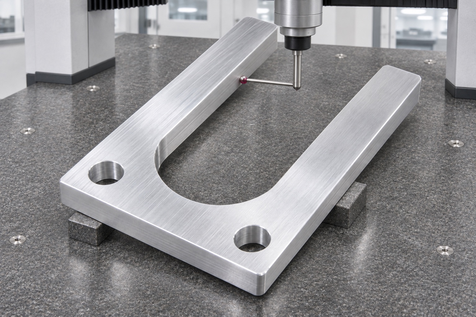
Finish edges while preserving the intended contacts
The proposed edge-finishing instruction would distinguish permitted edge breaks from the functional contact profile. Prong tips, the rounded root and both sides of the through-holes would be checked after loose chips were removed. Uncontrolled polishing would not be used to correct a dimensional mismatch or disguise an altered transition. If a contact line depended on an edge, the design owner would clarify how finishing should preserve it. Ordinary machining-edge inspection would not establish headset comfort, acoustic behavior or patient-contact suitability. Those questions would remain outside this representative mechanical case, even when a finished aluminum fork appeared smooth and visually consistent in a product photograph.
Keep the placement observation inert and limited
A supplementary bench review could place the identified dummy assembly on the inspected fork using an approved procedure. It would observe access and visible interference without powering a transducer, applying an invented service load or involving a person. A successful placement would not prove hearing-test accuracy or acoustic calibration. The team would note whether clearance or fixture flexibility could hide a profile discrepancy. Any conflict with dimensional results would prompt investigation against the drawing and dummy definition before rework. This limited observation can be useful for one fixture interface without being presented as a universal qualification of a medical headset support system.
Agree finish, cleaning and protective packing requirements
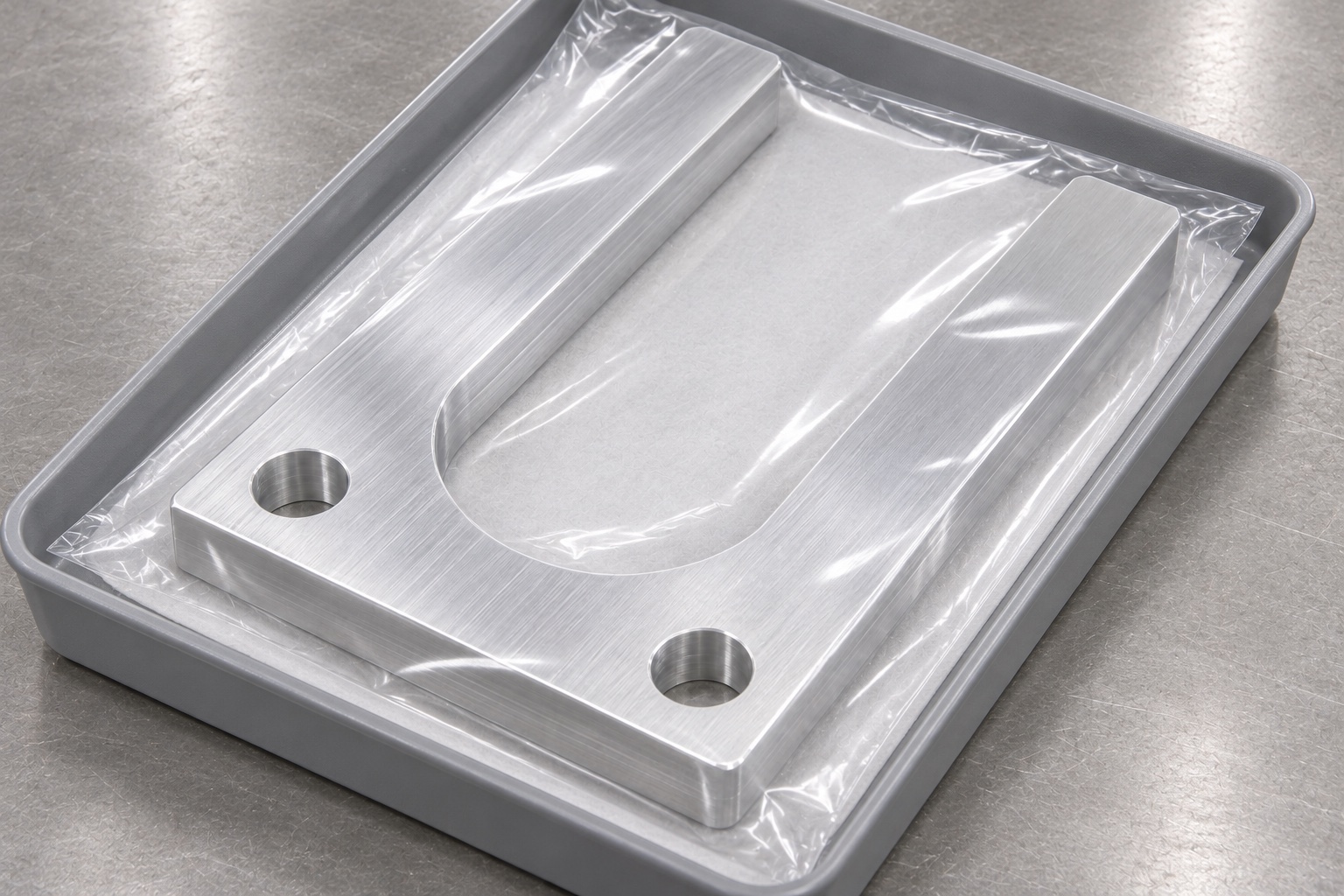
The hypothetical order would define whether the part remained bare machined or received a separately approved surface treatment. Any treatment would add masking, dimensional and inspection requirements before release. Cleaning and drying would follow the actual specification without unsupported sterile or validated-clean labels. Packaging would support the main body and protect the prongs from bending, rubbing or pressure from loose hardware. Identification would remain linked to the drawing revision and actual inspection evidence. The packaging image associated with this case communicates protective handling only; it does not establish a validated sterile barrier, completed shipment or a particular customer's packaging procedure.
Turn the proposal into an evidence-based real order
A real release would close the drawing, material, mounting, contact-profile, inspection and packaging decisions before manufacturing began. Actual first-article measurements and review would then determine whether the defined requirements were met. Any move beyond an inert bench fixture would require independent assessment by the responsible design owner. The representative case offers a structured way to request custom 6061 CNC fork manufacturing without inventing a delivery success story. It separates component milling, optional fixture development and application qualification so the supplier can quote concrete work and the buyer can evaluate real evidence against a controlled specification rather than an attractive but unverified product description.
FAQ
Does this describe a delivered headset project?
No. It is a representative manufacturing plan. No customer shipment, certification, calibration result or achieved production metric is asserted for this example.
Is the fork bent from aluminum sheet?
No. The representative geometry is a thick flat U-profile machined from stock, with two prongs, a rounded root and two plain mounting through-holes.
Which references connect the holes and prongs?
The released drawing must define the seating face, orientation and origin used for both the mounting pattern and contact profile. The supplier should not invent them.
Why inspect after unclamping?
Machining restraint may hide the actual prong condition. Acceptance must follow the drawing's specified support and component state rather than a convenient clamped appearance.
Can the dummy check establish acoustic calibration?
No. It only supplements a bounded mechanical placement observation. Calibration and hearing-test performance require separate defined equipment, procedures and evidence.
What is required before real work begins?
Approve the drawing and model, material and temper, dummy definition, contact and mounting requirements, finish scope, inspection methods, cleaning and packaging plan.

tanghangyun@oemach.com