
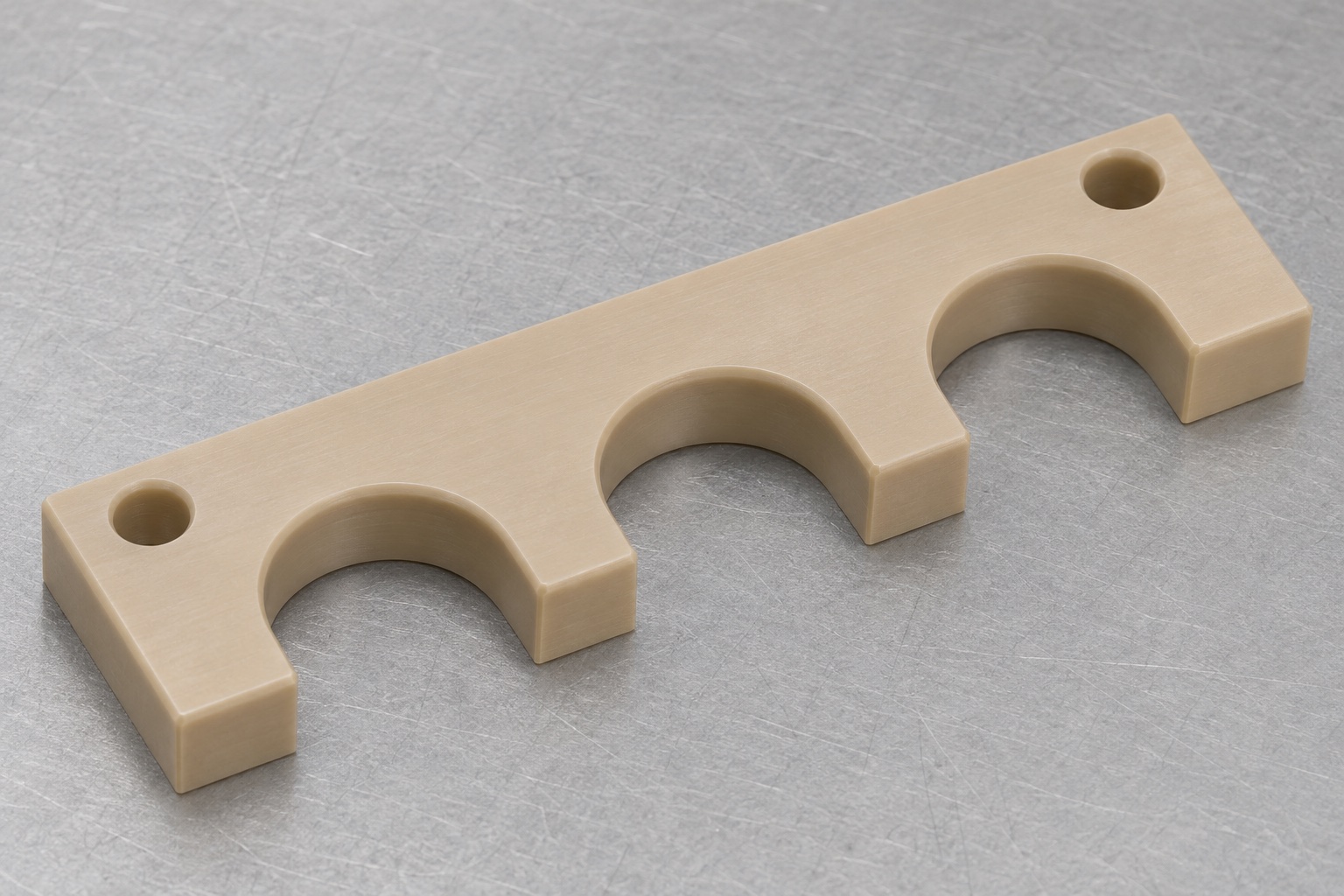
Scope of the representative three-slot comb
This representative CNC milling case proposes a natural unfilled PEEK cap staging comb for a non-operating laboratory bench fixture. The elongated bar has three identical open U-shaped slots along its front edge and two plain through mounting holes in the uncut rear strip. It uses inert cap references and is not a sealing or specimen-processing device. The case is not a delivered customer project and claims no certification, measured handling reliability, cryogenic performance or sterile process. An actual order would require approved drawings and acceptance criteria, with component machining kept separate from qualification of a complete laboratory workflow.

Review the cap and fixture interfaces
The proposed drawing review would collect controlled cap envelopes, insertion direction, required support regions and fixture mounting information. Local ribs, skirts or edge details would be included where they affect contact. The designer would state whether each cap seats against the slot root or another reference. Slot spacing would be related to the common mounting system rather than inferred from a photograph. The supplier would not treat one uncontrolled sample as evidence for an entire cap family. The review would also define the inert references used in an optional trial and separate these from operational sealing or specimen-handling requirements.
Identify the polymer before blank preparation
The material route would use an approved natural unfilled PEEK grade with identification retained through cutting and finishing. A tan plastic with unknown origin or an unspecified reinforced grade would not be substituted. Stock size would provide suitable workholding and machining allowance. The planner would consider the stiffness remaining after all three slots are opened. Any actual reagent, temperature or cleaning restriction would be reviewed as an explicit order requirement. This example does not infer cryogenic suitability, medical grade or biocompatibility from the polymer name. Those application properties require separate assessment of the exact grade and exposure conditions.
Establish supported reference faces
Initial operations would create the broad support face and secondary references while the blank retains sufficient stiffness. Fixture supports would be clean and recorded in the setup sheet. The rear strip would be held without bending the bar or preloading the future prongs into position. A sacrificial fixture could support through cutting if it provides safe access and does not trap debris beneath the part. Release checks would reveal any movement hidden by workholding. The proposed process would need physical first-piece inspection, rather than relying on a successful simulation or a visually convincing fixture arrangement as evidence of final conformance.
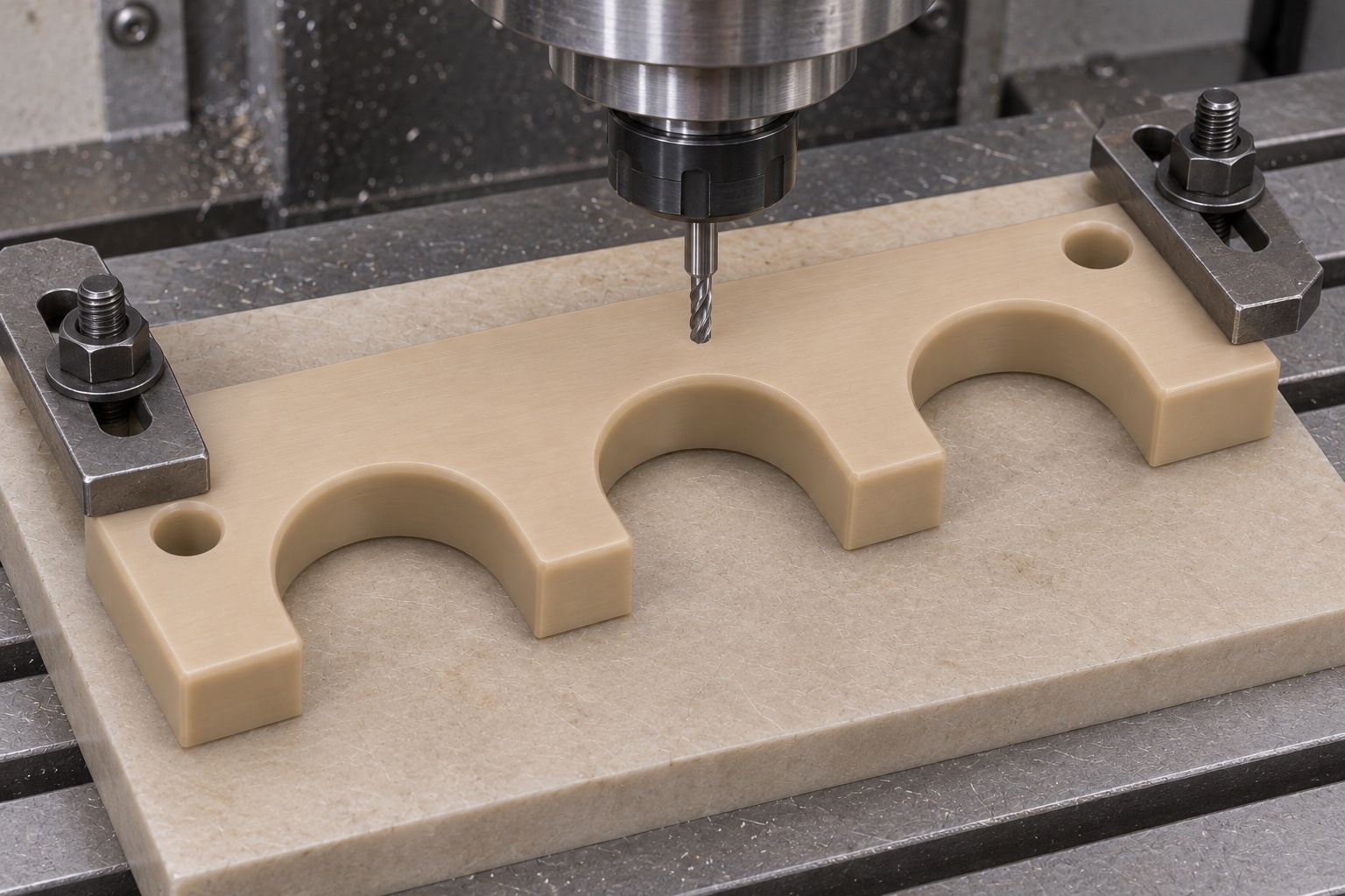
Rough the three openings with controlled allowance
The proposed roughing sequence would open the slots while preserving support in the rear strip and between adjacent profiles. Tool access and diameter would be reviewed against the curved roots and entry regions. Appropriate cutting conditions and chip evacuation would be selected for the actual PEEK grade and machine. Interim review would look for heat-related movement, damaged prong tips and unsupported edges. A release and reclamp step before finishing could be included if trial evidence justifies it. The process plan would record why the selected sequence is appropriate rather than prescribe universal machining parameters for every plastic comb.
Finish profiles and pattern location together
Final milling would address the three local profiles and their position relative to common datums. Root transitions and slot entrances would be inspected for ridges or remaining material that can alter first contact. The drawing would define any lead-in and edge treatment. Hand sanding to fit an unidentified cap would not replace a controlled finishing operation. If the tool cannot produce the approved geometry, engineering would select an alternative process or authorize a revision. This representative case includes no invented dimensional readings or capability claim. Actual acceptance would require measured evidence from the produced components and disposition of deviations.
Drill the two rear mounting holes
The rear strip would receive two plain through holes with axes normal to the support face. Their location and size would follow the approved datum scheme. The slot regions would remain free of unintended mounting features. Drill breakout would be supported where practical and both exits checked for burrs. Threads, countersinks and extra holes would not be added to accommodate available hardware without approval. The proposed inspection would verify the hole pattern separately from a screw-fit observation. A mounting method that pulls the comb into a different shape would need a defined restrained acceptance condition rather than an assumption that fastening corrects geometry.
Remove loose material without reshaping contacts
Edge finishing would cover slot mouths, roots, prong tips and mounting-hole exits. Suitable lighting and magnification would help identify attached plastic strands or a folded burr. The method would preserve the specified contact profile and avoid thinning slender regions through excessive abrasive work. Cleaning would remove chips and process residue to the agreed condition. It would not be described as sterilization or validated laboratory decontamination. If the order requires quantified cleanliness, that scope would need its own process and acceptance evidence. Functional damage would be held for review rather than polished until the original defect becomes difficult to identify.
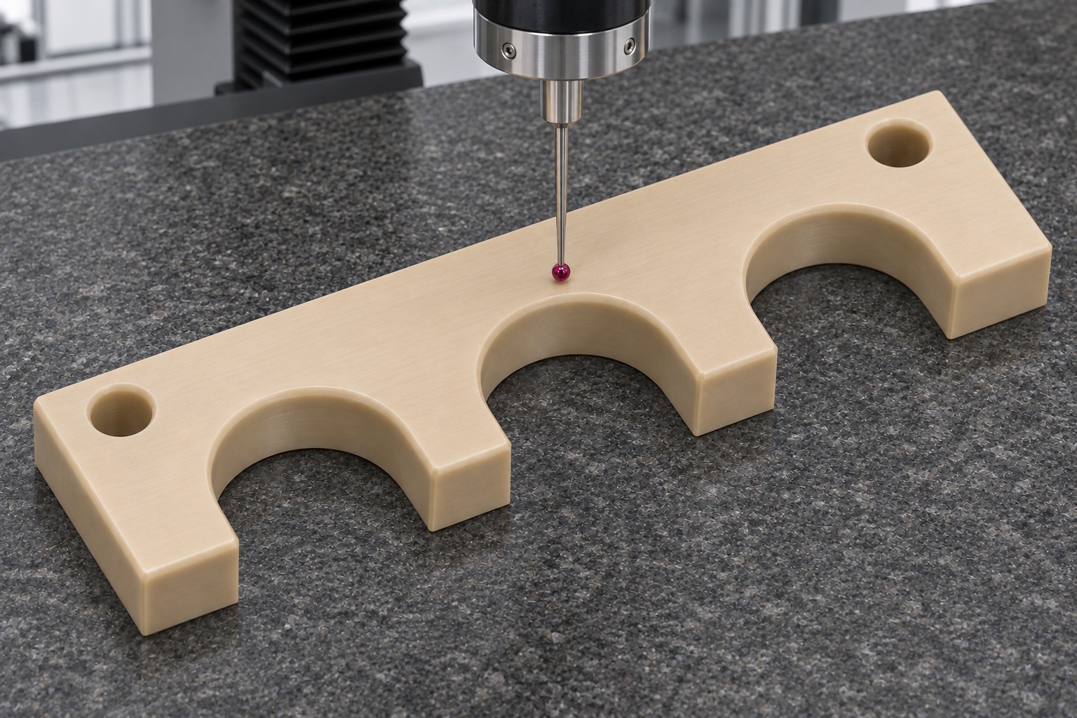
Inspect the conditioned released component
The proposed first-article report would identify the drawing revision, material record, measurement environment and support condition. Each slot profile and the complete center pattern would be evaluated from the approved references. Support-face form and rear-hole location would receive relevant checks. A low-force or noncontact method could be selected where probe loading would deflect a prong. This case supplies no fabricated measurements or acceptance rate. An actual release would require recorded results, with enough setup information to explain what was measured and permit meaningful comparison with a later incoming inspection performed under the agreed conditions.
Observe an inert manual staging trial
An optional unloaded trial could place identified inert cap references into the three openings on a non-operating fixture. The record would identify caps, comb, fixture and hardware revisions and note first-contact locations. Insertion and removal would be observed without specimens, an operating capper or a sealing process. The trial would not prove sterility, closure torque, cryogenic behavior or automated handling reliability. If a single position binds, the investigation would include its local profile and cap reference. If the whole pattern is displaced, the common datums and fixture should be checked before every opening is enlarged.
Control corrections and repeat-order changes
A confirmed local burr would receive approved removal and reinspection. A pitch error would require review of the common pattern references rather than uncontrolled enlargement of individual slots. Any material, cap revision, tooling or fixture change would be assessed before a repeat batch reuses old offsets. Inspection sampling would be agreed separately from pilot evaluation. The quotation would distinguish component machining, first-article reporting and development of an optional pattern fixture. Small quantities do not remove the need for traceable decisions. Component release would remain separate from approval of specimen handling, closure performance or a complete validated laboratory process.
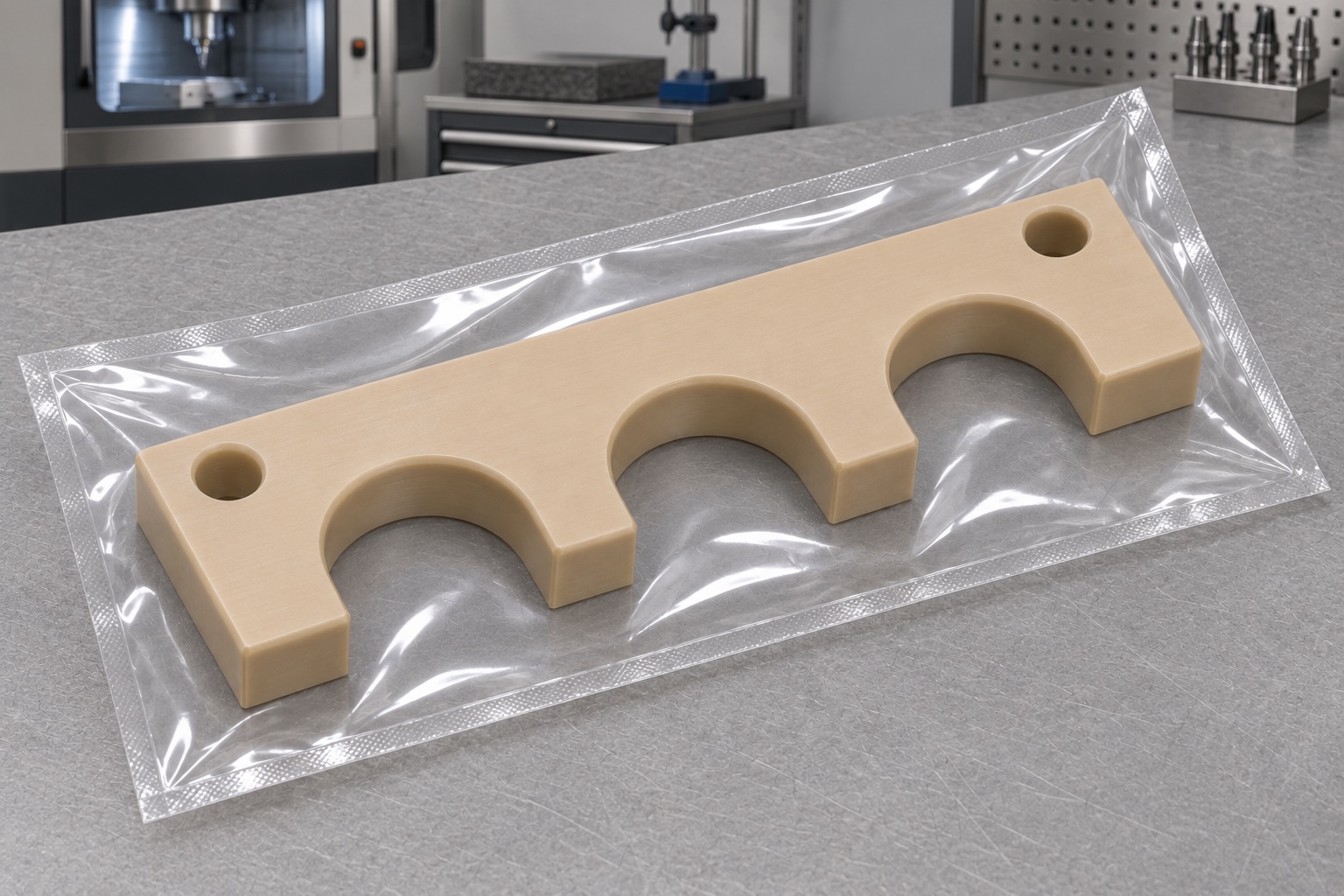
Protect prongs and traceability during dispatch
Packaging would support the main bar and keep the projecting prongs clear of straps, stacking loads and loose hardware. Contact profiles would be protected from scratching and packaging debris. Suitable clean bags and separators would follow the order's handling requirements without sterile labels. Revision, material and inspection records would remain associated with each packed batch. A final visual check would examine slot roots, tips and hole exits for retained chips or transit-sensitive damage. This representative route explains a proposed PEEK staging-comb manufacturing plan; it does not assert an actual shipment, certified design or measured operational result.
FAQ
Is this a delivered cryovial handling project?
No. It is a representative manufacturing proposal. It claims no customer shipment, certification, sterile workflow, measured reliability or cryogenic result.
What are the main geometric features?
Three open U-shaped slots share one front edge, while two plain through holes sit in the uncut rear strip of the elongated bar.
Why keep the cap references identified?
Different revisions or uncontrolled samples can have different contact envelopes. A traceable reference keeps observations connected to the approved interface.
Which inspection methods might be appropriate?
Use methods suited to slot profiles, center spacing and support geometry. Low-force or noncontact inspection can help avoid deflecting slender prongs.
Can every slot be widened to fix a pattern mismatch?
Not without investigation and approval. Widening can hide a datum or pitch error while reducing intended local support and altering the approved geometry.
What is needed for a firm manufacturing quotation?
Provide controlled drawing and CAD files, PEEK grade, quantity, cap envelopes, mounting information, finish, inspection deliverables and protective packaging requirements.

tanghangyun@oemach.com