
Representative scope without optical performance claims
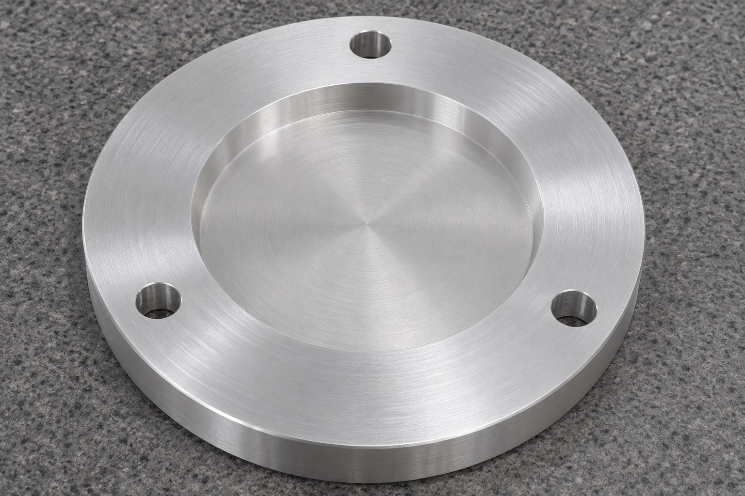
This representative case proposes a 6061 aluminum carrier disc for a non-operating optical coherence tomography service fixture. The part is circular, with a shallow blind pocket and three plain axial through holes equally spaced on the outer flange. The pocket supports an identified inert target envelope; it is not an optical target or calibration reference by itself. The case describes a manufacturing plan, not an actual customer delivery. No accuracy result, certification, imaging improvement or instrument approval is claimed. A real order would require approved geometry, material, finishing and acceptance requirements before the proposed operations could become a controlled manufacturing route.

Collect the target and fixture interfaces
The proposed drawing review would request the target envelope, seating face, removal path and mating fixture information. It would distinguish the pocket floor from the rear flange support plane and identify how the assembly is centered. The three-hole pattern would be reviewed for attachment clearance and any required angular relationship. A symmetrical pattern would not be assumed to provide unique clocking. Any uncertainty about optical spacing would remain with the designer rather than become an invented machining tolerance. The supplier would ask for a controlled target reference if an unloaded assembly check forms part of the agreed scope.
Specify material and incoming identity
The material route would use the specified 6061 alloy, temper and stock form with documentation appropriate to the order. The blank would be identified before cutting and remain associated with its lot through machining. Thickness allowance would account for establishing both reference faces and the blind pocket without relying on an uneven stock surface. The planner would consider whether the flange remains sufficiently supported after material removal. Additional chemical or surface restrictions would need explicit review. The alloy name alone would not be used to claim medical certification, cleaning compatibility, optical stability or electrical behavior in a complete service fixture.
Establish circular and planar references
A proposed first turning setup could establish the outside diameter and a reliable support face. The sequence would identify which features remain unfinished until the blank has been released and checked for movement. A later setup would recover the established references rather than rely on an unqualified chucking surface. The process planner would avoid concentrated gripping that bends the flange during cutting. Trial inspection would check the released condition against the drawing's support requirements. These decisions depend on the actual disc dimensions and stock history; the representative route does not prescribe a universal clamping force, cutting parameter or stress-management schedule.
Form the blind pocket and preserve its floor
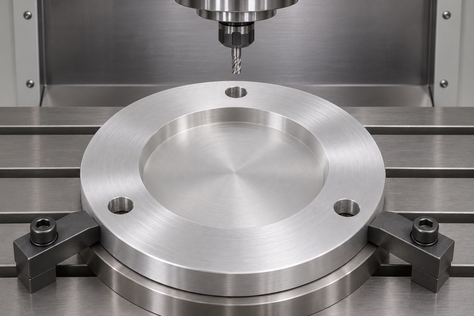
The pocket could be turned or milled using a process suited to its diameter, depth and corner geometry. Roughing would leave a defined finishing allowance, and the final depth would reference the approved support plane. Tool access and the remaining floor thickness would be reviewed before cutting. The route would preserve a solid floor rather than accidentally creating a through aperture. Root radii would be checked against the inert target envelope so a corner conflict does not prevent seating. Local polishing to hide machining marks would not be accepted if it changes floor form or the intended contact region.
Complete the three-hole flange pattern
The flange would receive three plain axial through holes at the specified pitch circle and angular spacing. A milling or drilling setup would locate them from the same approved geometry used to define the pocket and body. The process would not add countersinks, threads or locating fits without drawing approval. Drill exits would be supported where practical and checked for burrs that could lift the disc off its mating plane. An assembly bolt passing through one hole is not proof that the whole pattern is correct. The first-piece report would evaluate the required pattern characteristics with a documented datum setup.
Set finishing and cleanliness boundaries
The proposed route would specify the permitted edge breaks at the rim, pocket mouth and mounting holes. The pocket floor and flange support face would be protected from uncontrolled abrasive work. If a coating is required, the order would define masking, final acceptance condition and relevant post-treatment checks. The process would remove chips and residue from the blind pocket using methods compatible with the material and finish. This would be protective preparation to an agreed condition, not a claim of sterile processing. Any quantified cleanliness requirement would need its own sampling, method and acceptance evidence established before production.
Plan first-article dimensional evidence
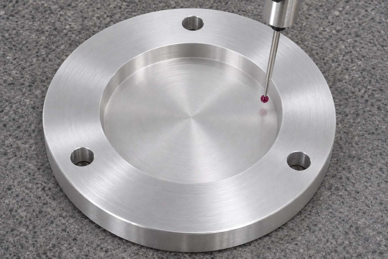
The proposed report would cover the drawing's relevant characteristics, potentially including disc thickness, outside diameter, flange form, pocket depth, floor orientation and mounting-hole pattern. Measurements would identify the support condition and reference alignment. Accessible coordinate checks could be supplemented by depth or form measurements where appropriate. The inspector would avoid using a corner blend as a floor reference. This representative case includes no fabricated numerical results or capability claim. An actual release would require recorded measurements of the produced component, with deviations handled through the approved process rather than inferred acceptable from a photograph or a successful tool-path simulation.
Observe seating with an inert target reference
An unloaded check could place an identified inert target envelope in the pocket on a non-operating fixture. The record would identify carrier, target reference, fixture and hardware revisions. It would observe insertion, removal and any rocking or interference. The check would not establish optical calibration, scanning quality or compatibility with a clinical OCT instrument. If the target fails to seat, the team would inspect the target radius and carrier corner geometry before enlarging the entire pocket. If fit changes after mounting, the review would include the flange support and fasteners. Drawing conformance and system qualification remain separate questions.
Resolve deviations before repeat machining
A floor-depth deviation would prompt review of the reference setup and actual remaining thickness. A mounting conflict would prompt a hole-pattern and fixture check rather than forced assembly. If a coating alters seating, the parties would compare final-condition measurements with the approved finishing requirements. Rework would need authorization and reinspection of affected characteristics. A successful fit with one uncontrolled target would not justify changing the carrier specification. The proposed process would preserve the reason for each decision so that a later batch can be evaluated against the same requirements instead of repeating undocumented manual adjustments.
Define the low-volume quotation package
The commercial scope would distinguish component manufacture, first-article inspection, finishing and development of any dedicated fit fixture. The RFQ would contain matching drawing and CAD revisions, material and temper, target envelope, mounting arrangement, quantity and packaging requirements. It would identify whether the buyer supplies the inert reference and who approves a deviation. Inspection sampling for repeat orders would be agreed separately from pilot evaluation. Small-batch precision aluminum machining remains dependent on clear interfaces and deliverables. The proposed quotation would not include optical calibration or equipment qualification unless those were separately specified services supported by the appropriate capability and evidence.
Dispatch without contaminating the blind pocket
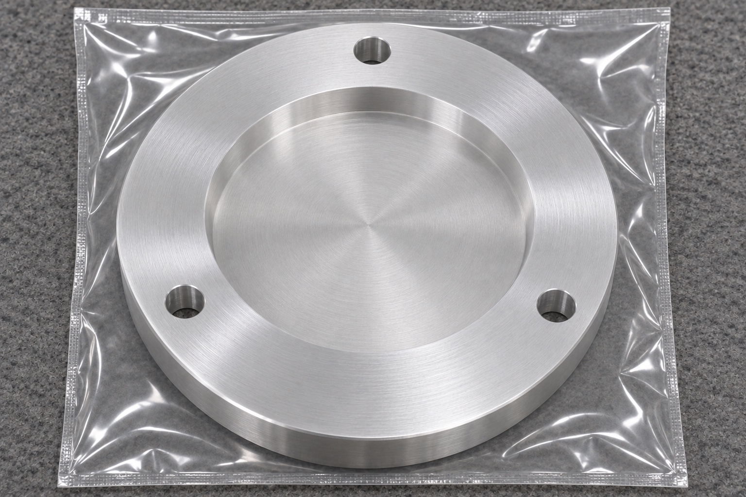
Each carrier would be protected so its rear flange face and pocket floor cannot rub against hard items. Loose screws and target references would be separated from the machined disc. Protective bags and separators would suit the agreed handling condition, with no unsupported sterile symbols. The release package would retain drawing revision, material identity and inspection records. A final visual check would look for retained debris, damaged hole exits and handling marks on seating surfaces. This representative manufacturing case explains a reviewable route for a custom OCT fixture carrier, without asserting an actual shipment or any validated optical performance of the completed instrument.
FAQ
Is this a real OCT instrument delivery report?
No. It is a representative machining plan. It claims no customer delivery, certification, measured optical result or approved instrument compatibility.
What are the main features of the proposed carrier?
A circular flange, one shallow blind central pocket with a solid floor, and three plain axial mounting holes define the representative geometry.
Is turning the only possible process?
No. Turning and milling can be combined according to geometry, access and workholding. The chosen route must be verified against the actual drawing.
What does the first-article report need to identify?
It should identify the drawing revision, measured characteristics, reference setup, support condition, inspection method and actual results required by the order.
Can a coating change be treated as cosmetic only?
Not automatically. Coating can change pocket clearance, depth and seating. The accepted final condition and relevant inspection must be agreed beforehand.
Does a flat-seating dummy target prove optical calibration?
No. It only supports a limited mechanical seating observation. Optical calibration and instrument qualification require separate controlled methods and evidence.

tanghangyun@oemach.com