
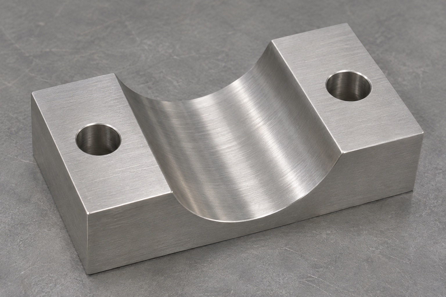
Scope of the representative saddle component
This representative machining case describes a proposed 316L pole saddle clamp half for a medical suction trolley accessory bench fixture. A straight semicylindrical groove runs through the upper body, with a flat mounting ear and one plain through hole on each side. The proposed scope covers the machined half and agreed inspection, not a complete clamp or operating trolley. There is no claimed customer delivery, measured holding force, certification or service result. An actual order would need approved drawings, mating information and acceptance criteria. The manufacturing route is intended to show how curved seating can be controlled without inventing assembly performance.

Gather the controlled mating geometry
The initial review would obtain the pole envelope, mating-half drawing, fastener specification and required ear relationship. It would identify the insertion direction and whether the halves close with an intentional gap. A photograph cannot establish these dimensions or the allowable variation of the pole. The parties would define which faces locate the half during inspection and which merely provide attachment clearance. Any uncertainty about how the clamp functions would be returned to the designer. The supplier's role is to translate approved geometry into a manufacturing and inspection plan, not to assign loading, tightening or medical equipment support requirements.
Establish a traceable material route
The proposed blank would use the specified 316L stock form and condition with material identification retained through cutting. Incoming review would check the required documentation and visible damage before scheduling machining. Sufficient allowance would remain for reference faces and safe workholding. The process planner would consider the section left beneath the curved seat and the stiffness of the mounting ears. Any additional surface treatment would be defined before production so its effect on final acceptance is understood. This example assigns no corrosion rating, validated cleaning method or medical material certification simply because the component is made from stainless steel.
Create stable references on the blank
Initial milling would establish the primary supporting face and the secondary references required by the drawing. The process would check seating after release rather than relying only on a clamped measurement. Clean fixture supports would prevent chips from being pressed into a reference surface. When the part is transferred to the groove operation, the setup sheet would show how the reference system is restored. Clamping loads would remain in sufficiently rigid regions, with tool clearance near both ears. A first-piece review would verify that the workholding arrangement does not hide deformation that appears only after the half is removed.
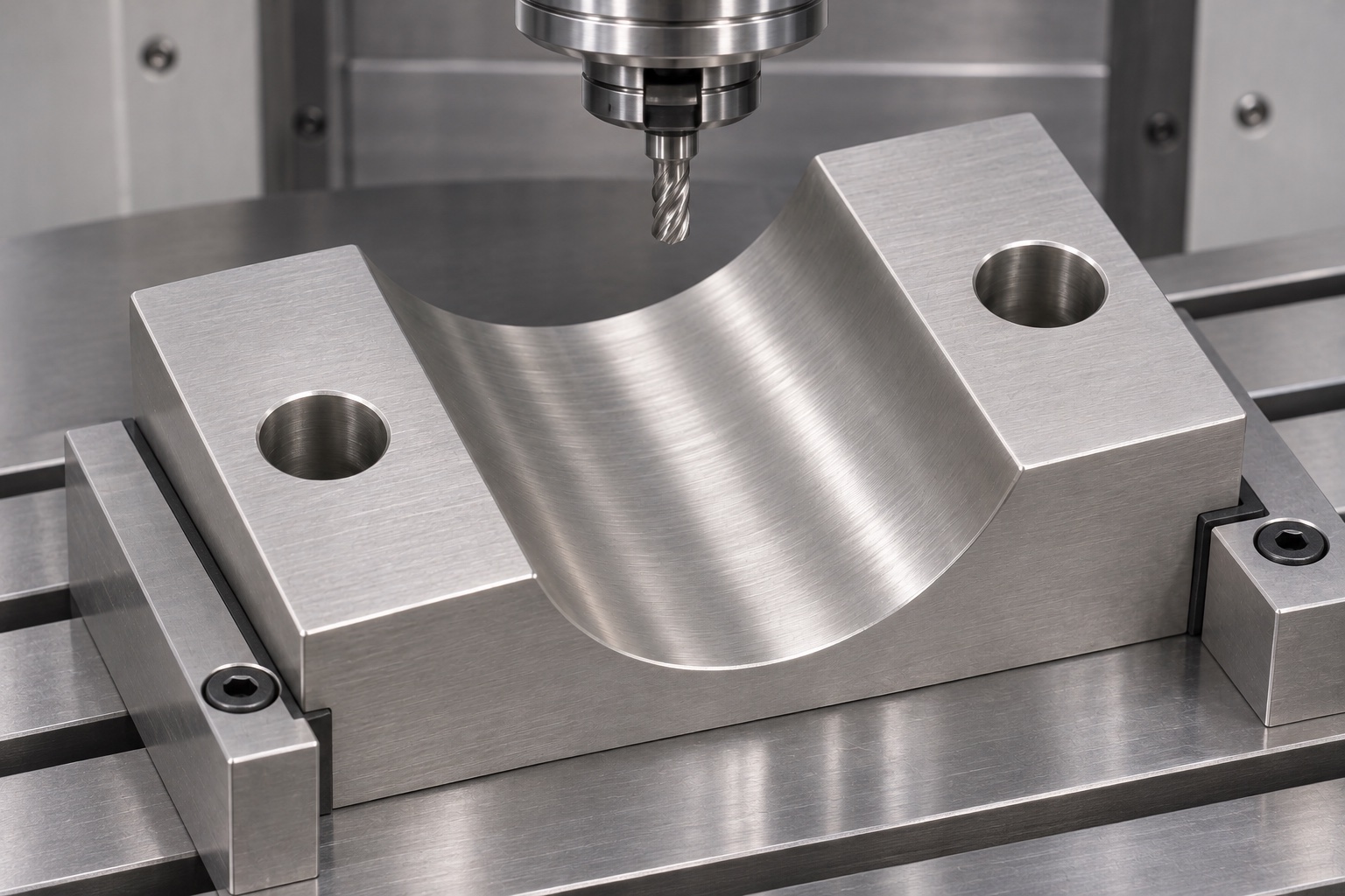
Rough the open cylindrical seat
The groove would be roughed while the body still has enough support, leaving a documented finishing allowance. The planner would compare suitable tool forms and access from the open ends rather than assume a particular cutter is always necessary. Tool reach, chip evacuation and cutting engagement would be reviewed for the selected stainless stock. A long overhang can compromise form even when the cutter reaches every point in a tool-path simulation. Interim checks would look for unexpected movement, recutting marks and unsupported edges. The proposed sequence would require physical first-piece evidence before being treated as an approved repeat-production process.
Finish the contact profile deliberately
The final groove operation would address the specified radius or profile, axis orientation and surface condition together. A continuous finishing path could reduce abrupt transitions, but the route would still need inspection at multiple sections. The open groove ends would be checked for ridges that could affect initial seating. Hand blending would not be used to make an unverified pole sample fit. If the drawing requires a form beyond the proposed tooling capability, engineering would authorize an alternative process or geometry change. No numerical accuracy or process capability result is supplied in this representative example; those records would come from actual inspected parts.
Produce the two plain mounting holes
The proposed hole operation would reference the same controlled geometry used to locate the curved seat. Each ear would receive one plain through hole. Hole size, spacing and any orientation requirement would follow the drawing. Drill breakout would be supported where practical, and both hole exits would be inspected for burrs. Countersinks, threads and additional dowel holes would not be added by assumption. The team would confirm that the selected hardware can pass without forcing the ears into alignment. A first-article report would measure the required hole characteristics separately from any optional unloaded assembly check.
Control edges and the final surface state
Deburring would target the groove mouths, outside handling edges and hole exits while preserving the designed cylindrical contact band. Magnified inspection would distinguish a folded burr from an acceptable edge break. Cleaning would remove process residue and trapped stainless chips to the agreed condition. If an approved treatment is ordered, the route would identify its supplier, documentation and the features requiring final checks afterward. This protective preparation would not be described as sterilization or a validated reprocessing cycle. Damaged contact edges would be held for disposition rather than polished until the original damage becomes difficult to identify.
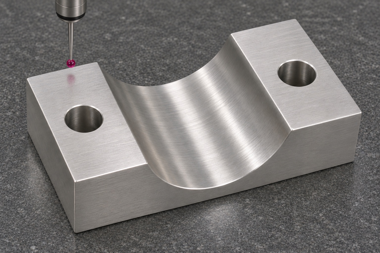
Document the first-piece geometry
The proposed report would identify the datum setup, support condition and measurement method. Groove profile would be checked at defined longitudinal stations to assess local form and orientation. Ear faces, hole positions and other drawing characteristics would receive their own results. A coordinate or form measurement system would need appropriate access and a suitable probe strategy. The report would refer to the actual drawing revision, not only a machine program. This case contains no invented measurements or acceptance rate. An actual release would require recorded evidence and approved handling of any deviation before parts are accepted for dispatch.
Perform a limited bench assembly review
An identified inert pole reference and approved mating half could be used to observe seating without operational loads. The review would record component revisions, hardware and the condition in which the halves are brought together. Unexpected first contact, ear rocking or interference at a groove end would be documented before modifying anything. The trial would not demonstrate holding strength, resistance to vibration, transport safety or suitability for patient-adjacent equipment. If fit changes after fastening, the investigation would include the reference pole and mating half. A part that meets its drawing should not be reworked simply to compensate for an incompatible external component.
Make repeat-order controls explicit
For a later batch, the supplier would confirm the drawing, pole envelope, mating-half revision, material and finish before reusing the process. Tool replacement or fixture changes would receive review proportional to their effect on profile and alignment. Inspection sampling would be agreed rather than inferred from a successful pilot. Quote documents would separate component manufacturing, first-article reporting and development of any dedicated fit fixture. Small quantities do not eliminate the need for traceable interfaces. The aim is a repeatable and reviewable machining scope, with assembly performance and equipment qualification remaining separate deliverables under the responsible organization's plan.
Protect the curved seat during dispatch
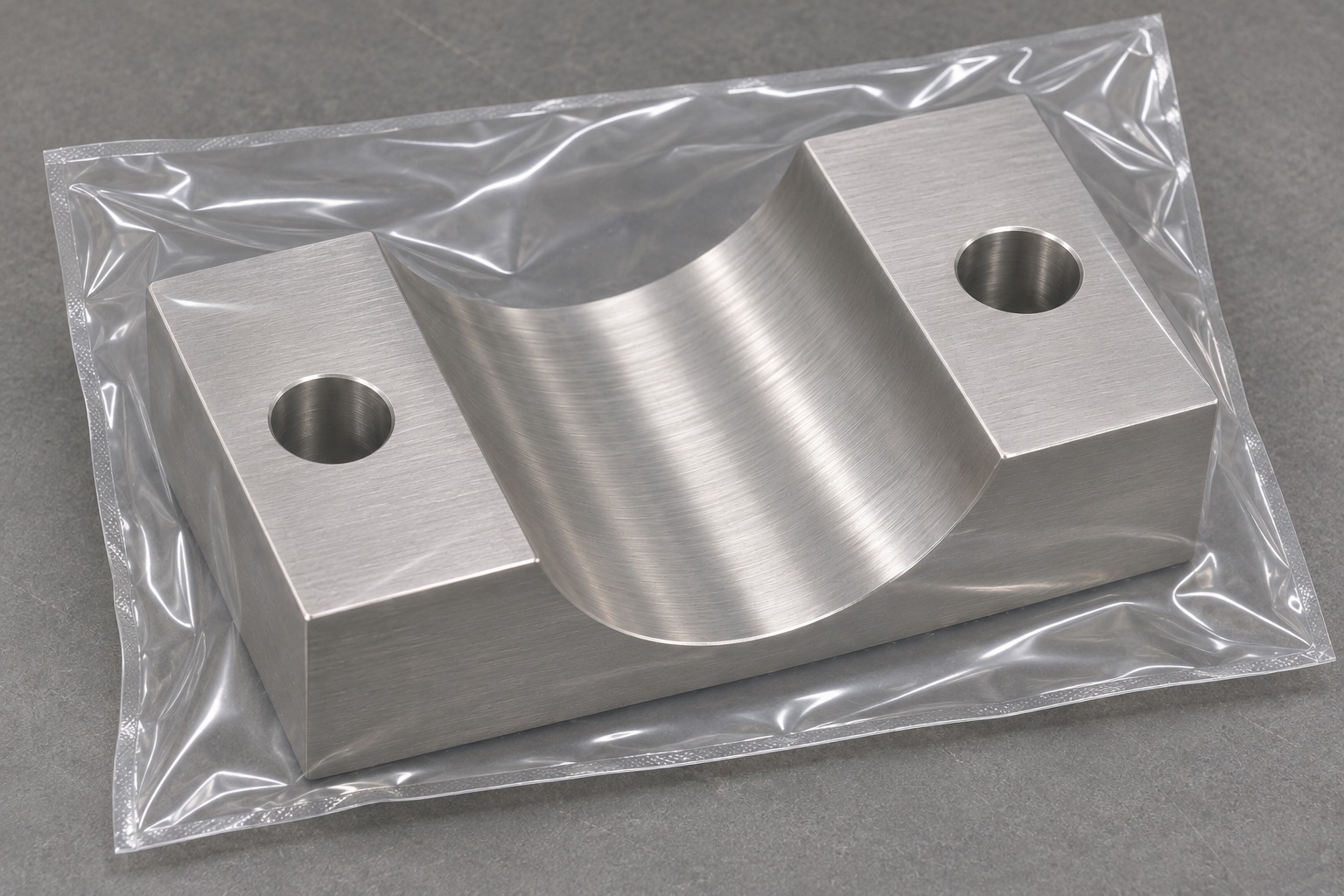
Packaging would support the rigid body and prevent the groove, mounting faces and ears from rubbing against another part. Loose screws and pole coupons would be packed separately. Clean protective bags or separators would be selected to match the agreed handling requirements, without sterile claims. Revision, material identification and inspection documentation would remain linked to the packed component. A final visual review would check for retained chips and transit-sensitive edges. This representative route explains the manufacturing decisions behind a custom stainless pole saddle half; it does not assert an actual shipment, certified clamp design or demonstrated service capability.
FAQ
Is this a delivered medical trolley project?
No. It is a representative manufacturing proposal. No actual customer, shipment, certification, holding force or service result is claimed.
Is the proposed part a complete clamp?
No. It is one saddle half. The mating half, fasteners, pole envelope and complete assembly requirements must be defined separately.
Why keep the material lot linked to the blank?
Traceability prevents unidentified stock from being treated as the specified 316L material and connects the finished component with agreed procurement documentation.
Which features need separate inspection?
The drawing may require groove profile and orientation, supporting faces, ear geometry and hole positions. A pole fit alone does not measure them all.
Can a fitting problem be solved by polishing the seat?
Not without investigation and approval. Local polishing can alter contact geometry while concealing a mating-part or reference error.
What is required for a firm machining quotation?
Provide controlled drawings, material, quantity, pole and mating-half information, fasteners, final surface state, inspection deliverables and protective packaging requirements.

tanghangyun@oemach.com