
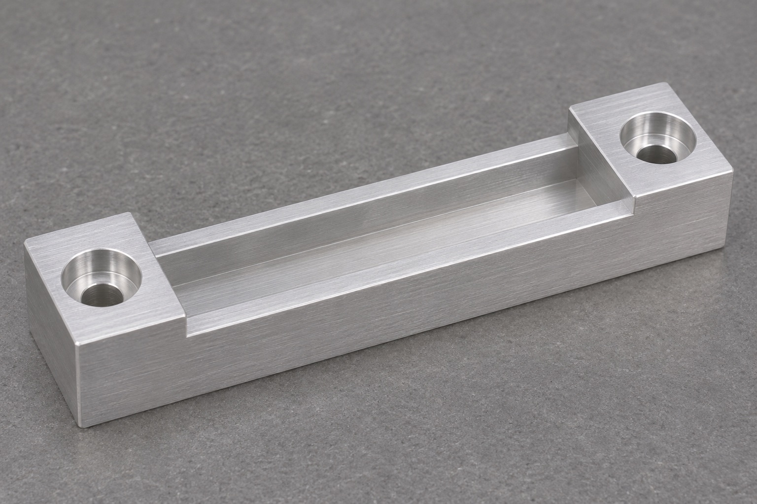
Define the representative part
This representative machining case covers a short 6061 support shoe for a removable microplate washer splash guard. A top groove with a flat floor and parallel walls receives the lower edge. The two end bosses contain counterbored through holes that secure the shoe to a separate mount. The proposal covers machining and dimensional inspection with an optional non-operational fixture trial. It does not describe a customer delivery, certified safety component or verified wash result. The released drawing and guard and fastener envelopes would control fit. The shoe is neither a liquid seal nor part of the fluid circuit.

Capture the assembly interfaces
Obtain the allowable guard edge thickness, edge radius and any retained covering. Confirm that the guard is inserted from above rather than pushed through a closed end. Identify side contacts, intended floor contact and clearance at the bosses. The drawing should separate groove location from the clearance holes used for attachment. Note how the shoe locates on its base if the fasteners do not constrain it. Obtain the screw form and permitted head height so the recess can be inspected with the correct reference. Keep the guard and screw revisions with the fixture definition.
Select and orient the billet
Use the approved 6061 stock form and temper and identify its lot before cutting blanks. Start with enough margin for a stable grip and a clean base finish. Do not add bulky temporary stock if it prevents a short stiff cutter from reaching the groove. Place the rough blank on verified supports and check whether it rocks. A bent blank under excessive clamping can measure flat when restrained and move afterward. If material movement appears during the pilot, revise the roughing sequence and measure after release. Keep material and setup observations in the same pilot record.
Create the mounting reference
Face the base and prepare a side or end reference before finishing the upper groove. Support the blank directly beneath the force of the cut. Clean the fixture contact points before relocating the part. If the part must be flipped, identify the orientation on the work instruction and verify that the new setup measures from the true seating face. Confirm cutter and clamp clearance at both bosses. A small witness from a stop can be acceptable only outside protected surfaces and only as allowed. Check the base condition before trusting it to control the final groove location.
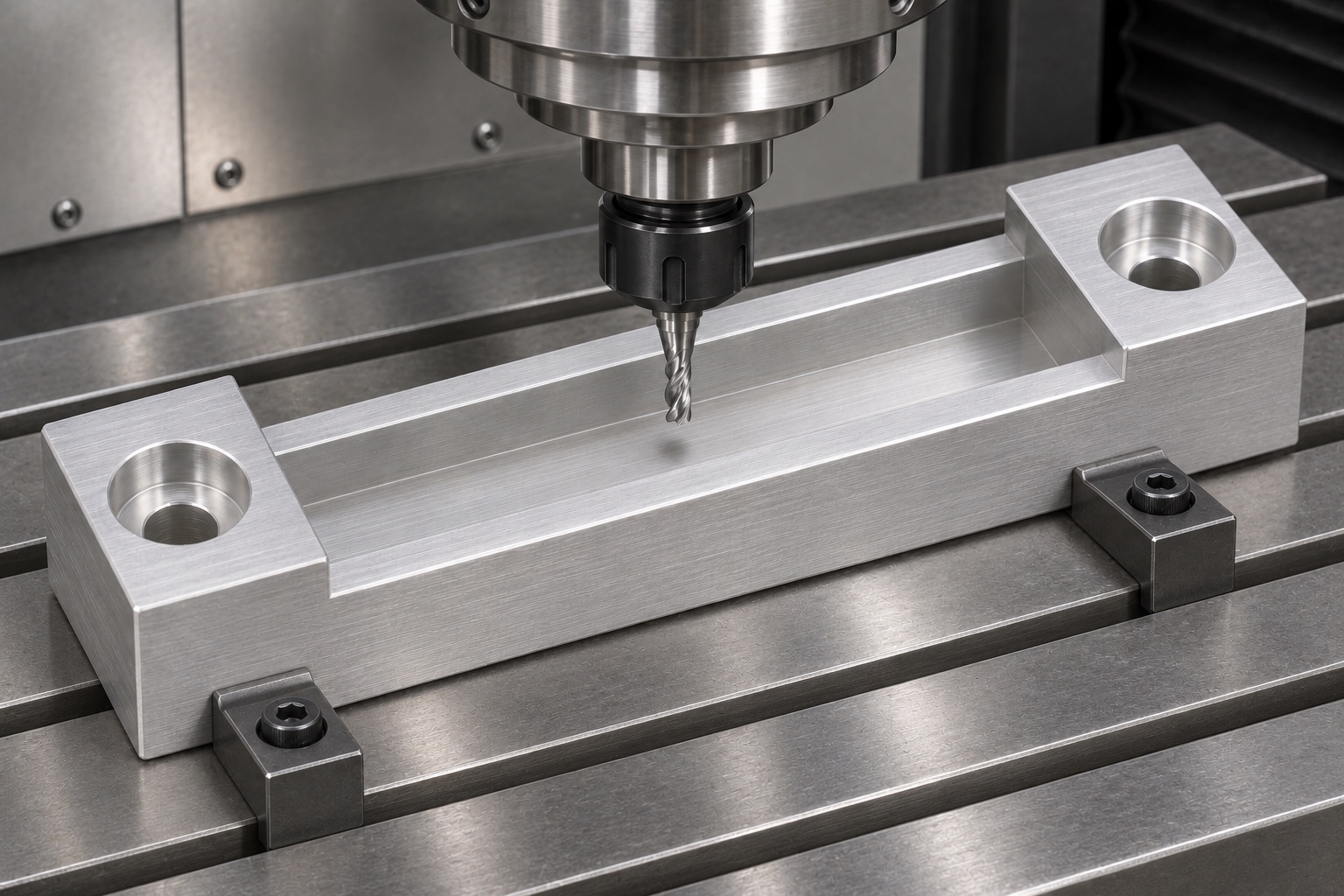
Machine the groove and mounting bosses
Rough the groove with allowance on both walls and floor. Finish the floor and then the working walls with a tool path that avoids heavy side load. Plan chip evacuation throughout the groove, especially near the end bosses. Set the corner radius to the approved value and check for a ridge where floor passes meet. Drill the through holes and finish the counterbore seats from the drawing references. Verify access to the fasteners without forcing the guard into the groove. The programmed width, depth or screw size is not evidence of the result; check the first piece on the agreed inspection equipment.
Treat the edges according to their function
Remove raised material from the groove entrance and from both through-hole exits without opening the fit region. Check the inner ends near the bosses for trapped chips and uncontrolled tool marks. Keep the bottom of each counterbore suitable for contact with its specified fastener. If finish is required, agree on the drawing's masking areas and final acceptance state. Do not treat a shiny surface as evidence of flatness, coating quality or chemical compatibility. Move the parts in separate containers between machining and inspection so the narrow groove rails do not contact other hardware or an abrasive tray.
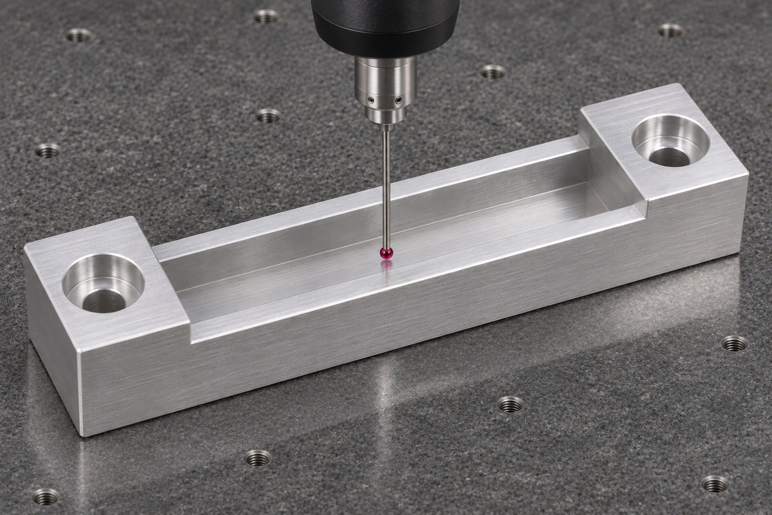
Configure a stable inspection support
Use the shoe's actual mounting face and the specified side reference. Verify that the measuring support and clamp do not distort the rails or seat. Check the width and depth of the groove at both ends and at a central station if the drawing calls for it. Select an instrument that reaches the intended height on the walls. Measure the slot position from the agreed mounting references, not from the appearance of equal wall thickness. Check boss height and counterbore depth separately when either can affect screw clearance. Document restraint, finish and methods in the report.
Compare geometric and functional evidence
A clean guard coupon can verify removable fit under a specific condition. Select the required envelope and record its revision. If a sample passes even though a measured position misses the drawing, investigate the angle and looseness of the coupon rather than accepting it automatically. If a conforming shoe will not accept a valid coupon, check corner radii and the base for burrs. Compare the results on the unmounted part and the fixture. A single pass is diagnostic evidence, not proof of repeat capability. Retain real measured values only when the pilot part and measuring setup exist.
Test mounting without operating the washer
Set the shoe on a representative bracket and use the specified screws. Check that the underside seats without rocking and that the heads clear the test guard. Insert and remove the guard at agreed limits without forcing. Observe whether screw tightening changes the profile or whether a head projects into the removal path. If a conflict is found, document the affected assembly condition and refer it to the design owner. Do not immerse or operate a clinical or diagnostic instrument for this check. The example makes no inference about washing, liquid containment, device reliability or sanitation.
Decide what belongs in repeat controls
Retain the stock condition, fixture reference, wall finishing method and measuring locations from an approved pilot. Check the first piece after a tool or fixture change and after a finish change that can affect fit. Where the customer accepts a quick production coupon, maintain a separate method to verify groove geometry and the coupon's own condition. Record any edge correction with its authorization so repeat orders do not inherit an undocumented change. Use the drawing and the agreed inspection plan to decide lot sampling. No production tolerance guarantees or cycle-time results are implied for the proposed job.
Document the purchase scope
Quote the machined shoes, finish and inspection separately if their scope can vary. State whether the buyer will supply the dummy guard, the bracket and the fasteners. List controlled width, depth, face condition, and the mounting hole and screw seat features to be reported. Identify the materials and packaging evidence required at receipt. This helps a buyer compare a basic CNC milling quotation with a proposal that also includes functional checks. Agree on variation limits before any supplier builds a gauge. Avoid broad descriptions like laboratory grade without stating how the required surfaces or cleanliness will be accepted.
Protect the groove during transit
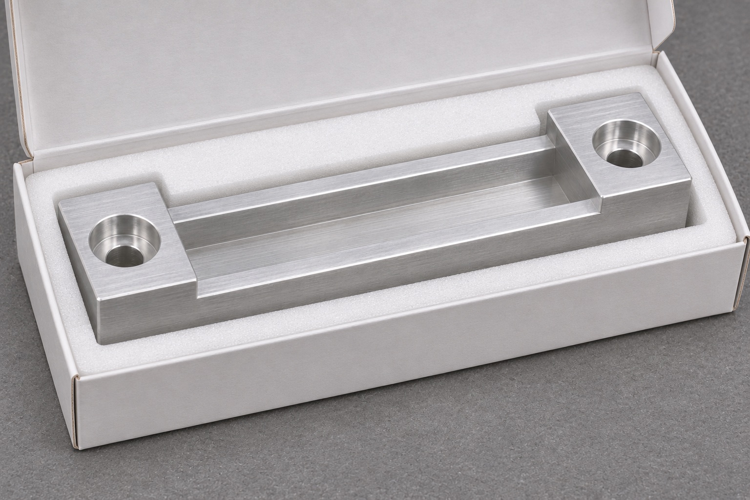
Use an individual fitted foam recess or divided tray with support under the rigid base. Remove loose fasteners from the part compartment so they cannot strike the walls. Keep any tape away from the groove and datum face. Match the outer label to part revision and material lot and retain the accepted inspection results separately from packing material. Ordinary packaging is for physical protection, not sterilization. At receiving, check the groove edge and screw seats before inserting a coupon. If the package shows damage, quarantine the affected part and recheck slot geometry instead of judging by insertion force alone.
FAQ
Was the support machined for a real customer?
This is a representative case, not a record of shipment. The route and inspection inputs describe how a proposed component could be produced.
Why reference the slot floor to the underside?
That relationship controls guard seating height on the fixture. A measurement from a cosmetic top face may not protect installed height.
What is the most useful pilot specimen?
Use an identified shoe plus a guard coupon and fasteners representing the released interfaces. Record the actual state and dimensions of each.
Can a burr under the shoe cause binding?
Yes. It can tip the installed groove relative to the guard. Inspect both mating surfaces before modifying the slot.
Does a functioning dummy guard establish equipment safety?
No. It only provides mechanical fit evidence for the stated assembly condition. The equipment owner is responsible for separate system evaluation.
Does the proposed route require a coating?
No coating is assumed. Follow the specified finish and verify the locating features in their accepted final state.

tanghangyun@oemach.com