
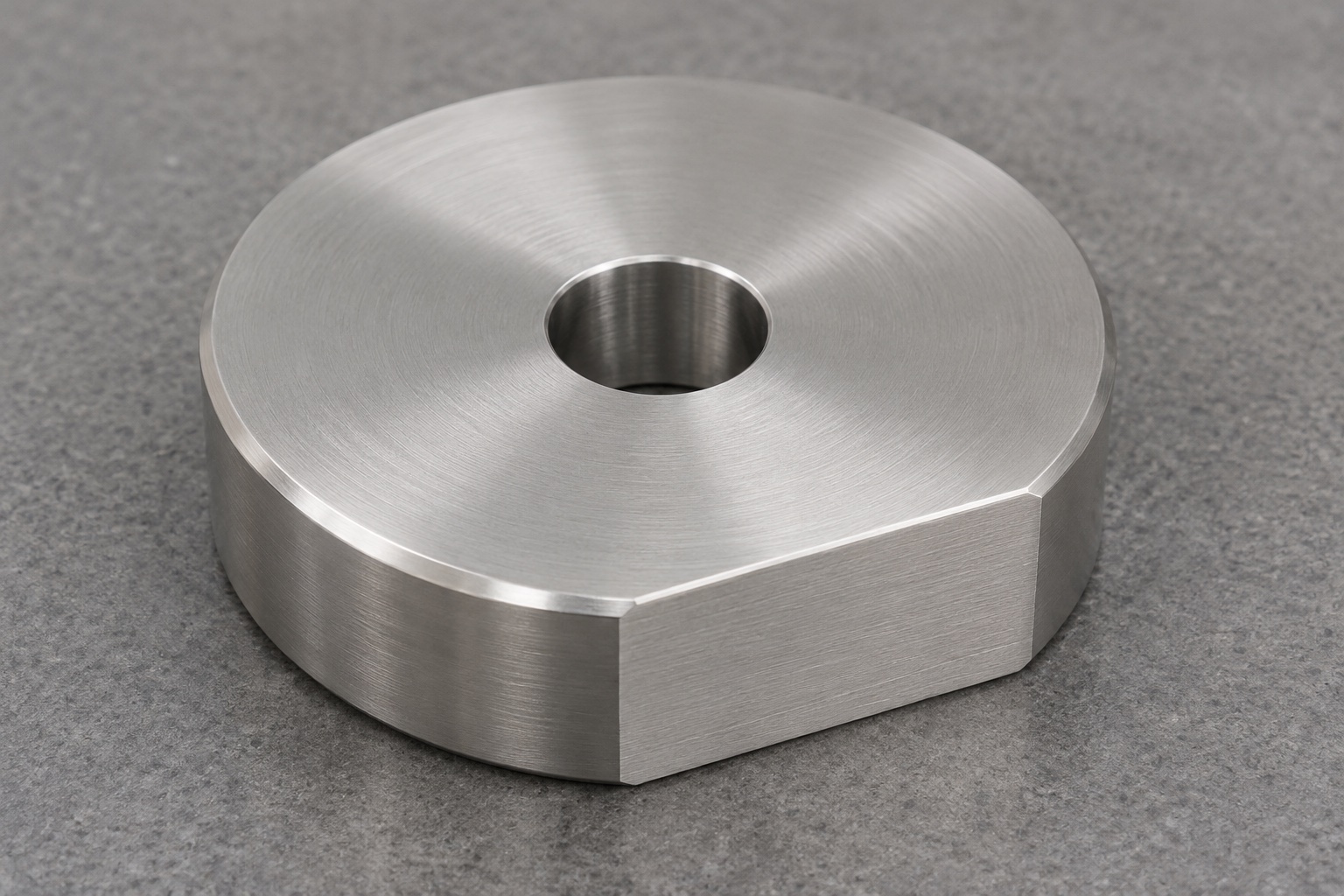
Scope of the example
This representative case describes a short stainless steel indexing master for a non-operational radiotherapy rail development bench. The proposed part is a 316L disk with a through bore, a seating face and a single milled chord flat. A test fixture can engage the bore with a pin and use the flat to check a directional stop. The case does not describe a shipped customer order, certified instrument, patient accessory or verified equipment result. It shows how to convert the intended bench contact into a machining route, coordinate measurement and protected shipment. Actual limits belong to the approved drawing.

Request the working fixture interfaces
Ask for the fixture pin size and usable engagement, the support face and the stop location. Determine whether the disk is always inserted from the same side. If either face can be mistaken for the seat, identify the intended orientation by documentation or a marking permitted outside the functional region. Include the access envelope around the disk so the shop can check whether the outer diameter is a limit or a functional fit. A drawing showing the chord length but not its offset from the bore axis may be insufficient to assess whether the disk will meet the stop.
Prepare a traceable turning blank
Select 316L in the specified form and condition and record the lot before cutting. Leave stock for face cleanup and safe holding. Review the finished wall section around the bore and plan support accordingly. Avoid using a serrated grip on surfaces that must survive as functional contacts. Keep the stock direction and roughing sequence consistent in the pilot lot so a dimensional shift can be investigated. If there is a requirement for finish treatment later, keep the blank and post-treatment records linked. No stock condition or surface treatment is assumed beyond what the buyer specifies.
Establish the face and through bore
Face the blank and turn the accessible outside diameter and bore with a common spindle reference where practical. Rough the bore with enough allowance for a stable finishing pass. Keep the underside contact annulus clear of pulled chips and remove any loose edge material using the agreed edge method. If it is necessary to reverse the disk to finish the second face, use soft jaws or a suitable support that does not mark the working bore. Check seat flatness and bore geometry after release. A machine offset record supports repeat work but is not dimensional proof on its own.
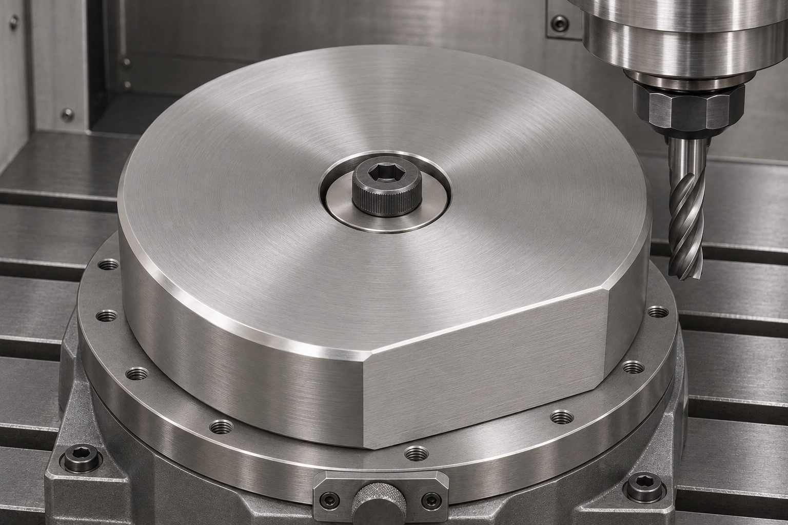
Mill a single chord from the bore axis
Seat the turned disk on clean pads and locate it from the bore. A central clamp can retain it if pad placement supports the load and the cutter clears the hardware. Probe or otherwise verify the bore center in the milling setup. Use the machining program to place the chord flat at the approved distance from that axis. Inspect the first part at the flat's functional height. If a roughing pass leaves a witness near the chord ends, adjust the route based on result and drawing rather than sanding the whole surface. Save both the support positions and locating method for repeat work.
Deburr without changing the stop surface
Inspect the two flat transitions, outer perimeter, both bore openings and the contact face. Remove loose raised material without cutting back into the functional flat. A short controlled edge break is preferable to broad blending when a narrow stop needs a reliable contact band. Use finishing tools that avoid transferring contamination into the stainless steel surface. If another approved process follows, confirm which features must be reevaluated afterward. Protect accepted parts from bare-steel contact and grit while they are moved to inspection. Do not use abrasive rubbing to make a damaged datum look uniform.
Measure the three functional features
Use the released drawing to define the face, bore and flat. Measure the seat and check that the fixture does not force the disk flat. Capture enough cylindrical surface to establish bore size and axis at the required depths. Collect points on the central useful flat rather than the rounded transitions. Report the offset from the bore axis and the angular relationship that the drawing specifies to the seating face. If shape matters beyond these checks, agree on sampling and the fitting method. Record units, temperature when relevant and the explicit revision of each measurement program.
Run a separate bench fit
The optional fit check uses a non-operational rail mock-up with clean pin and stop surfaces. Seat the disk under the stated load and observe the order in which the surfaces make contact. Use a known fixture state rather than tightening parts until they appear to fit. Repeat insertion after removing the disk and check for scratches or a shift in seating. If push force is required unexpectedly, inspect burrs and the pin envelope before reopening the bore. The proposed test is limited to the stated interface. It does not verify a treatment system or qualify any clinical procedure.
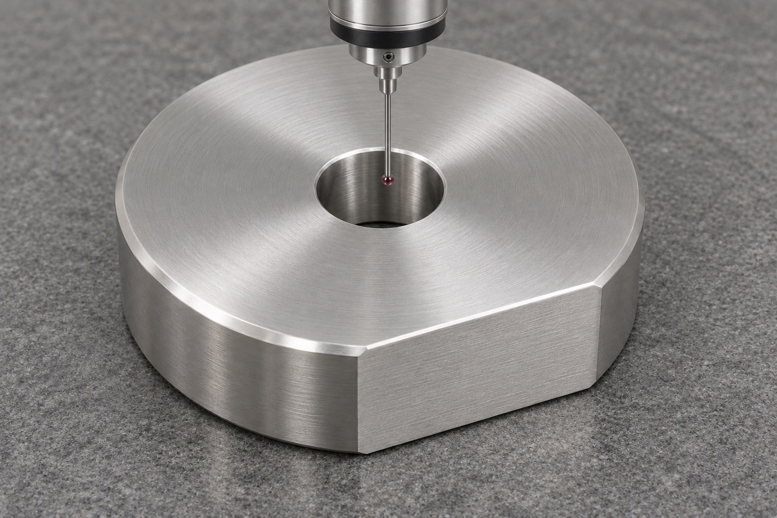
Review possible deviations with the right evidence
If plug passage is good but the flat contacts early, compare its measured offset with the fixture stop setting. If center offset depends on clamp force, review the seating pads or clamping design rather than adjusting the cutting tool. If the disk rocks in only one direction, check for a local high point on the face and document it. Keep a record of whether a defect occurs before or after finishing and handling. Change one variable at a time when practical so the correction can be reproduced on the next first piece. Escalate drawing changes rather than widening acceptance limits informally.
Establish a low-volume control plan
For a small pilot, separate the initial setup and measurement development from recurring machining. The trial can compare an indexed turn-mill route with separate turning and milling. Review fixture access and whether the bore and seat can be transferred without marks. Require rechecks after any change of insert, locator or finish that could affect the working surfaces. Keep a verified master apart from normal production pieces if the buyer requests one. Define the verification method before treating it as a reference. No rate, tolerance capability or longevity result is asserted in this proposed route.
Define purchase and delivery scope
Provide stock identity, drawing revision, dimensional report and any separately ordered fixture fit record. Specify whether the buyer supplies the bench rail, pin or stop and whether the part will be sent back after trial. Clarify the required receipt condition, identification location and protection. Include prices for requested fixture development and special inspection so quotes are comparable. Decide how a deviation will be recorded and who can authorize a change. A supplier should not need to infer a treatment-device requirement from the part name. Explicitly limit the proposal to the mechanical master and stated evidence.
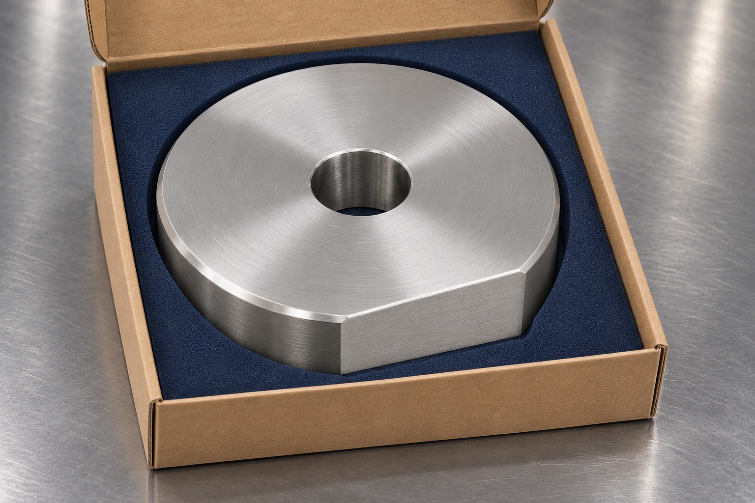
Ship on the broad face with protected edges
Pack the disk in a smooth fitted recess that supports its broad face without point loads and prevents movement into screws or pins. Keep the bore clean and avoid a divider edge pressing against the flat. Preserve the identity of each checked piece and link outer labels to the dimensional record. This package protects the part in transit and is not sterile packaging. At receiving, inspect the seat and bore for handling marks, compare the ID to the report and confirm the intended face. Hold any damaged part for review before putting it into a fixture.
FAQ
Is this an actual treatment equipment project?
No. It is a representative fabrication plan for a non-operational bench fixture aid, without a customer claim or operating equipment result.
Why cut the flat after turning?
The bore and seating face give useful references for locating the flat. When a different sequence is selected, show how these relationships are retained.
Can the master be evaluated on a shop pin?
Only for the condition that pin actually represents. Record its dimensions and purpose; use a separate approved method for geometry not checked by the pin.
What should the report say about the flat?
State the offset from the specified axis, flat sampling region and drawing-defined relationship to the seating face. Include the measurement setup.
Is passivation required for every part?
No treatment is assumed here. Follow the released material and finish requirements, including any checks needed after the approved treatment.
Can this part calibrate patient positioning?
No. The proposed check concerns a development fixture and has no patient positioning or clinical validation scope.

tanghangyun@oemach.com