
Limit the case to removable tooling
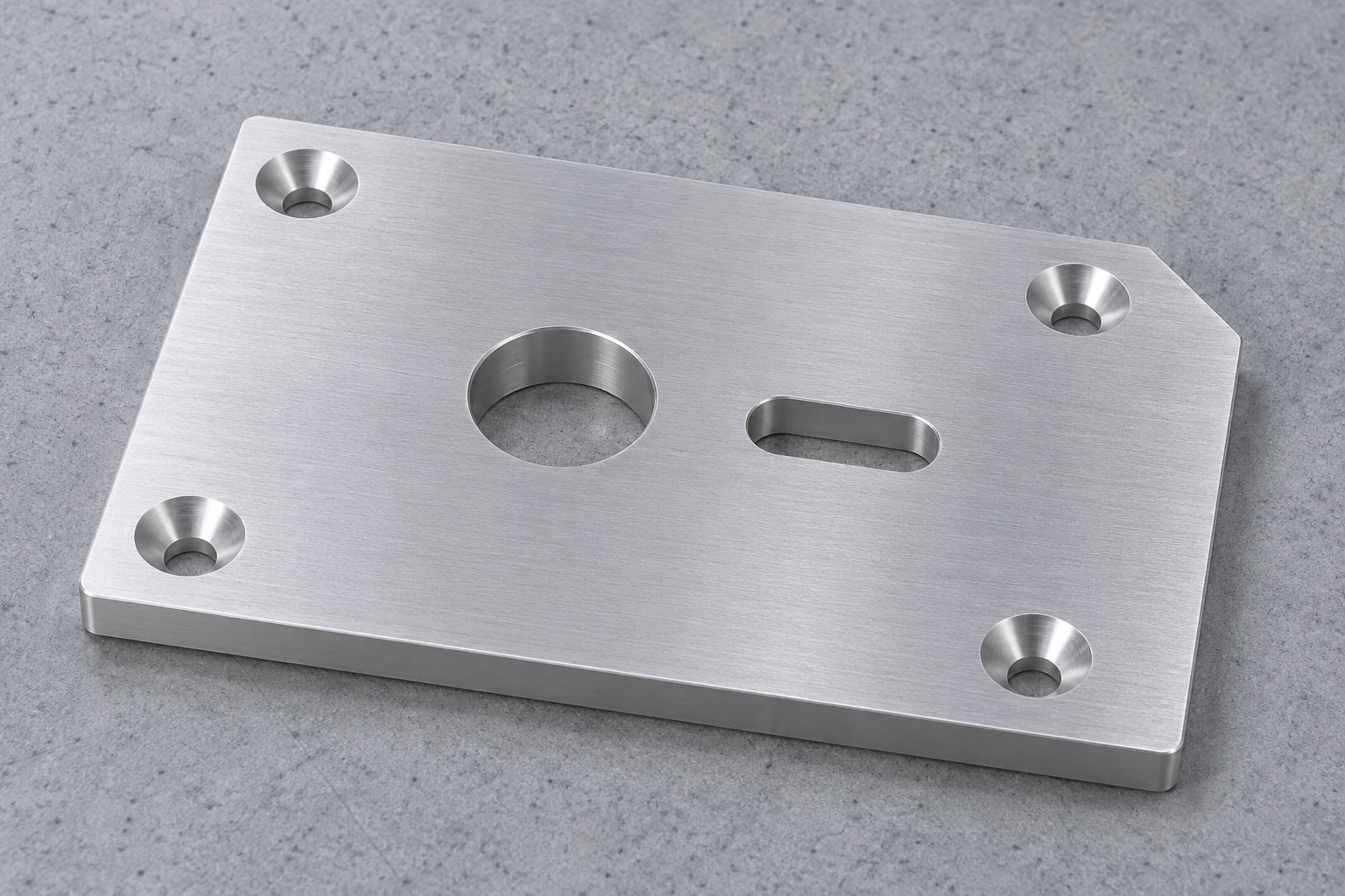
This representative manufacturing example covers a shallow 6061 locator plate used in an off-device service fixture for an anesthesia workstation access panel. Its working features are a flat seating face, one round locator bore, one oblong locator slot, four countersunk screw holes and a clipped orientation corner. The plate is tooling for a bench fixture, not an operating part of an anesthesia machine. No customer project, certification or equipment result is represented. The aim is to show how a shop can plan CNC milling and check the mechanical interface from a controlled drawing and a defined pair of fixture pins.

Identify inputs before selecting tools
Obtain the fixture plate drawing, pin sizes and permitted center spacing, mounting screws and the test panel envelope. Clarify which plate face touches the fixture base and whether the top face supports anything. Mark the slot direction on the inspection view. Identify which corner is clipped so the part cannot be installed backwards on a matching fixture where the key is used. Ask whether the drawing controls screw-head protrusion by dimension or fit. A missing screw specification can produce misleading results because a different head angle changes how far the screw sits in a compliant countersink.
Prepare material with enough finish stock
Choose 6061 in the specified temper and form. Link each pilot piece to its stock lot and record visible bow or damage before machining. Saw the blank with enough material to clean the perimeter while keeping useful support margins. Do not force the raw plate flat under heavy clamps just to establish a convenient reference. Check whether face machining on both sides is needed to achieve the required finished condition. Record the order of removal and any interim flatness checks. If the purchased stock is already close to thickness, agree how much can be removed before starting.
Build a stable first setup
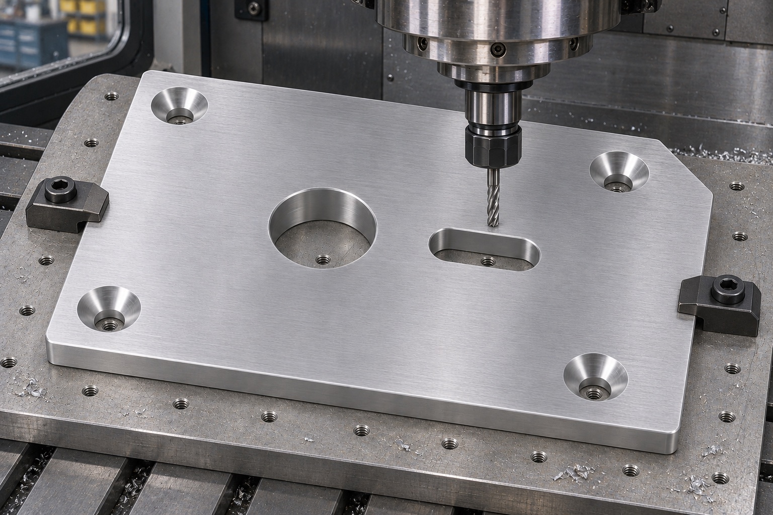
Support the blank on a suitable sacrificial plate or on verified pads positioned under the cutting region. Establish the working face and accessible edges while keeping clamps outside the bore and slot toolpaths. Rough both broad faces if the pilot reveals movement, then recheck the relaxed blank before the final face cut. Put the correct side up when transferring to the locator operation. Chips under the plate can shift its seating condition and lead to a false setup reference, so clean the contact surfaces before each loading. Confirm the support does not leave marks in any specified seating region.
Cut the two locators together
Use a common coordinate setup for the round bore and slot where possible. Rough the bore and use the finishing method appropriate to its size and fit. Rough the slot with clearance for a separate finish pass along its straight walls. Confirm the cutter can clear the rounded ends without altering the working wall spacing. Inspect the actual slot direction and working length from the drawing references rather than using the programmed tool path as evidence. If a tool needs to approach from the opposite face, verify that the datum transfer preserves the relationship between the two locators.
Complete mounting and orientation details
Machine the four screw holes and countersinks with the drawing-specific tools. Check head seating with the agreed screw or a suitable gauge before making depth corrections. Keep a defined edge break at the exits and make the clipped corner without altering any adjacent datum edge. Remove chips from both locator openings and inspect for raised material on the underside. If the slot meets size but a burr catches a pin, correct the edge to the approved requirement rather than widening the slot. Separate cosmetic finish requirements from the limits that protect seating and the locating pair.
Verify surface condition before final acceptance
The route can leave the plate as machined or include a specified finish. If anodizing or another treatment is required, agree on the relevant masking and final measurement conditions before cutting the pilot. Protect the seating face against handling marks between operations. Check the clipped corner and edges after any treatment and confirm that the openings are free of residue. A part accepted before finishing should not automatically be accepted afterward when a coated surface affects fit. The example does not assert a coating class, corrosion resistance result, cleanliness class or electrical function.
Report the geometry from functional datums
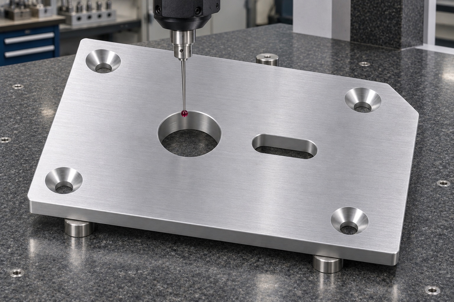
Inspect the base face without pushing it flat. Determine bore size and center position, and measure slot width and direction at identified points on the straight walls. Verify clearance at the slot ends. Measure the fastener features and overall thickness as required. Use the same references in the report as the approved drawing so a reviewer can compare the readings directly. A fixture with master pins can supplement the dimensional report but should not replace it without agreement. Identify the actual instrument, support condition and finish state for the pilot rather than quoting nominal values as results.
Check insertion and removal on a bench fixture
Use a fixture base or non-operational coupon with the specified locating pins. Insert the plate by hand using the agreed clearance condition and confirm it can be removed without prying. Check for rocking before and after applying the specified mounting condition. Inspect how the screw heads sit relative to the panel envelope. If both pins enter but the plate shifts when tightened, look at the countersinks and mating threads. This is a proposed mechanical check of tooling interfaces only. No operating anesthesia equipment, gas connection or clinical evaluation is part of the example.
Decide how to manage pilot deviations
If the slot traps the second pin, check its direction against the actual pin line before changing width. If a screw sits high, verify head angle, depth and burrs first. If the plate bows after release, compare the stock, clamp force and face cutting sequence. Change the process in a documented order so the cause is apparent. Repeat the relevant checks on a new pilot piece. For low-volume CNC milling, retain the fixture references and finish measurement plan for reorder lots. A successful pilot fit is not a statistical capability result and does not replace the agreed sampling plan.
Define the deliverables for a repeat order
Request the controlled part revision, stock identification and a dimensional report covering the agreed features. If the supplier runs a fit trial, list the fixture and screw revisions and the recorded fit condition. Clarify which side supplies the master pins and whether the price includes the fixture setup, final finish and packaging. Ask for separate prototype and repeat prices when comparing machining routes. A single-piece setup can be economical for a small pilot, while a dedicated fixture may help repeat lots if the demand justifies it. No such cost or cycle-time result is assumed in this case.
Ship without loading the plate
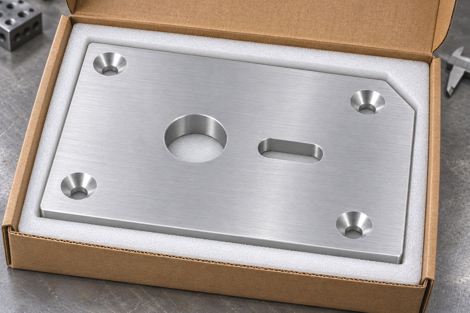
Place each plate on a clean flat support or in an individual tray, using separators that cannot rub the locator edges. Store loose hardware in a separate compartment. Keep the plate clear of local pressure from carton closures or bands. Carry the revision and material lot on the outer label or traveler. These measures prevent handling damage; they are not sterile packaging. At receipt, check the bore and slot edges and confirm the underside is clean before repeating a fit check. If there are impact marks or visible bow, assess the plate before attempting to force it onto the fixture pins.
FAQ
Is this a documented anesthesia equipment delivery?
No. It is a representative example of machining a removable bench fixture plate. It does not describe a customer or a working device.
Why cut both locators from one setup?
It can reduce error from moving the part between the bore and slot operations. The finished geometry still needs inspection.
How can the correct slot direction be verified?
Measure both straight slot walls relative to the agreed datum system. Compare the direction with the actual line between the fixture pins.
What can a representative screw show?
It can reveal head protrusion or an incorrect seating condition under the defined assembly. It does not replace required measurements of the countersink.
Is the plate always anodized?
No. Use the released finish specification and verify the locators in their final accepted condition.
Does the fixture check prove device performance?
No. It addresses fit and access in a non-operational bench setup, not any medical, electrical or pneumatic function.

tanghangyun@oemach.com