
Define the representative component
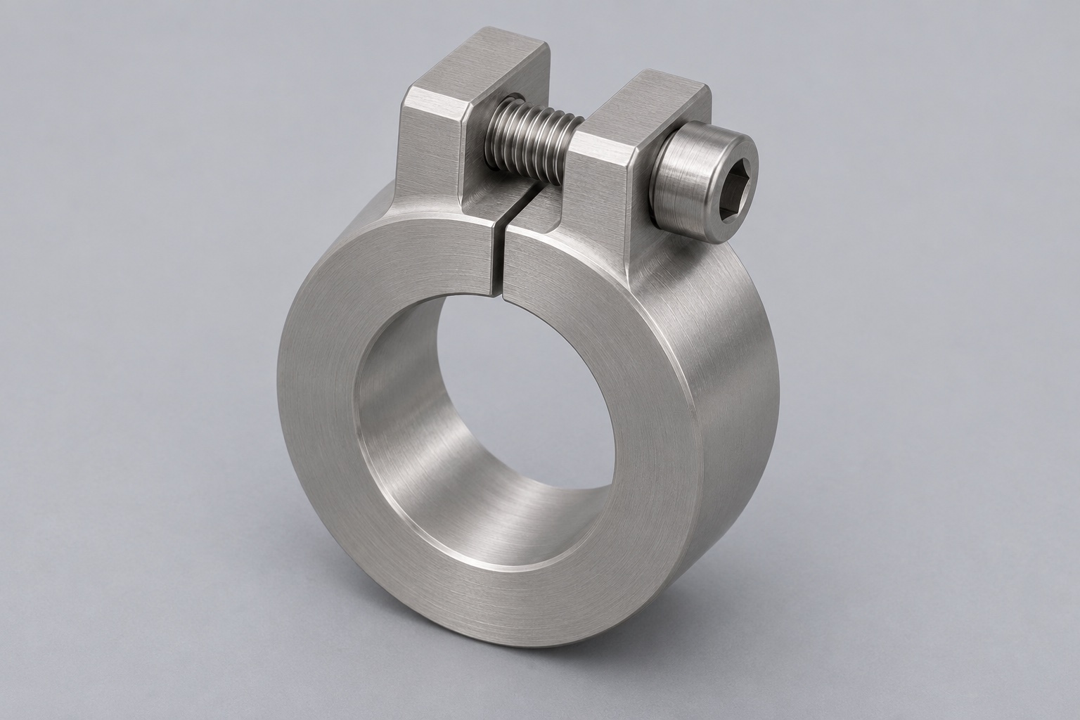
This representative machining case concerns a 316L stainless steel split collar for a dental handpiece service fixture. A dummy barrel seats through the collar and against a face reference in the bench assembly. A radial slit allows two integral ears to close around the barrel with one transverse screw. The scope is limited to a proposed component, its tooling and a dimensional inspection plan. It does not describe a customer delivery, a certified fixture or testing of a working handpiece. A new design should identify the support load, mating geometry and acceptable contact locations before any tolerances are finalized.

Describe the interfaces for quoting
Provide a section through the collar, an axial view of the slit and an ear detail showing which side is threaded. Show the barrel shoulder and the bench seating face on a separate assembly drawing. Treat the body circumference as a gripping surface only where it does not define assembly location. Include the head-seat relief and driver envelope because the screw may be difficult to reach next to a bench wall. State whether a liner will be present in production. If it will, request the collar drawing and liner drawing at matching revisions so the radial stack and available closing travel can be checked together.
Build an allowance plan for the pilot
Start from a piece of traceable 316L stock wide enough to leave the ears integral. Determine the cutoff allowance and mark the stock lot on the traveler, not on the functional face. For the pilot, reserve material at the bore for a second finish operation if the trial reveals substantial release after slitting. The amount is a process decision to be tested, not a universal machining allowance. A small pilot can compare a closed-ring finish sequence with a supported post-slit finish sequence. Use the same acceptance setup for both so fixture force cannot explain the apparent difference between the two routes.
Set up the main CNC turning operation
Face the blank, rough and finish the accessible cylindrical features, and check for chips caught at the bore entry. Keep the seating face and bore in one turning setup if the selected workholding can reach both. Where the external stock is not round after preparation, use a fixture appropriate to the blank and balanced spindle conditions. Do not spin an unbalanced billet as if it were round bar. Verify access for the boring bar and record the first measurement after the part cools. If transfer to milling relies on a cylindrical feature, mark that feature and its intended clamp band on the setup sheet.
Transfer to the ear and screw setup
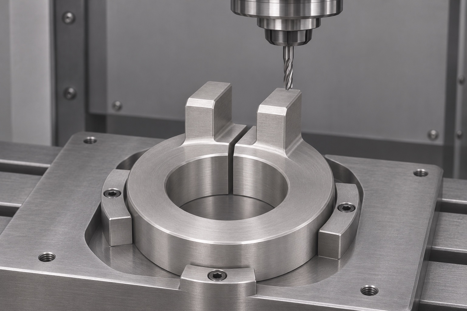
A cradle supports the lower part of the body against the axial stop. A fixed clocking reference positions the ear stock without using a cosmetic witness mark. Machine the ear sides with the upper stock still connected. Drill the clearance and thread preparation features from the agreed direction, and use a tool reach that avoids the opposite ear and fixture. Check head seating on the clearance side before cutting the radial split. If opposite-side access is necessary, verify the locating references after the move. Keep this change in the setup record so the next lot does not depend on an operator reconstructing the alignment from memory.
Open the slit with a controlled toolpath
The blank remains on its face support with clamps reacting through the body, not the ears. A narrow tool opens the radial path to the bore. Select the tool and entry to avoid an exit burr that is difficult to reach in the bore. Keep chip evacuation active at the intersection and measure slit width after removing the part. If the split is tapered or drifts, check tool deflection and fixture seating before changing nominal tool compensation. Measure the bore again without screw load. This comparison separates a slit-cut problem from general closure after stock release; the fixes for the two conditions are not interchangeable.
Finish the bore intersections and threads
Make the specified edge breaks at the bore mouth and both slit intersections, keeping the axial seat intact. Use suitable magnification to look for turned-over metal where the cutter exits. Verify that the threaded ear accepts the appropriate inspection gauge without running the production screw through debris. Clean according to the agreed component requirements and keep the collar away from steel chips during handling. Any specified post-machining treatment belongs on the router with its timing and acceptance criteria. A bright visual finish should not substitute for a roughness check or lead to polishing a fit surface beyond the drawing.
Compare three useful measurements
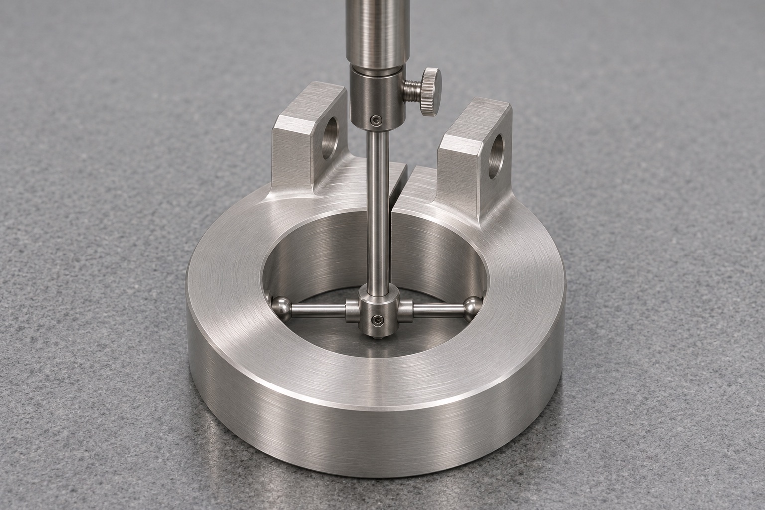
The proposed first-article report records bore size at identified depths and directions, free slit width at defined locations and the axial face relationship to the bore. Inspect the ring resting naturally on the face with the screw removed. If a scan is needed, define the unusable arc adjacent to the slit and the chamfer exclusion. Inspect the transverse holes and head seat from their own reference surfaces. Use the same part ID to connect the post-turning and final readings so changes can be traced. Do not report a numerical result for a feature until the instrument, state and sampling method have been agreed.
Use a separate fit fixture
An approved dummy barrel with known diameter and shoulder condition can check installation access and the closing sequence. Note whether it slides in, bottoms on the intended face and releases once the screw is backed off. A screw that reaches the bottom of a blind thread before closing the ears is a different issue from a collar with excess free clearance. Record the difference and check the screw length before remachining the bore. Where a liner is fitted, evaluate the collar with the specified liner rather than drawing conclusions from a metal-to-metal trial. No vibration, life or equipment safety result is asserted here.
Establish decision points before scaling
If the free bore stays within the specified condition and the closing travel is adequate on the pilot, retain the simpler route. If it varies with the slit operation, review the stock condition, cutting order and clamping load first. If finishing after the slit is necessary, qualify a nest that repeats without forcing the collar back into a round shape. Recheck after release and record the setup. For low-volume CNC machining, these decisions can matter more to cost than spindle cycle time alone. Retain the first accepted condition and a reference setup sheet so additional batches can be compared on the same basis.
Define what a supplier should return
Request the agreed dimensional report, material identification and the revision of any customer-supplied dummy barrel or liner used for fit checks. Clarify whether the quotation includes the pinch screw, a master, a dedicated nest or only the machined collar. Split initial fixture cost from repeat production cost when comparing routes. List process questions separately from acceptance requirements; a proposed change in slit or screw design needs review before it becomes a drawing change. If the application has restrictions on surface residues or contact marks, state the inspection method in the purchase package rather than relying on broad language like medical grade.
Pack without loading the ears
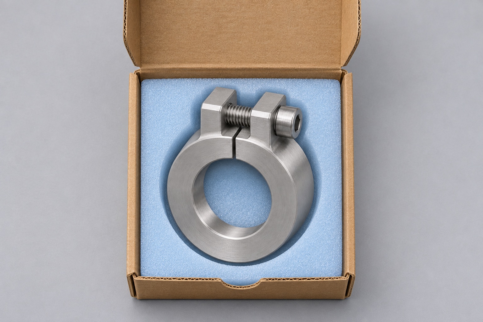
Use one recess per collar with support under the rigid body. Keep the screw in a separate pocket if it is supplied loose and avoid any movement against the bore. If it ships fitted, agree the retention condition so the ears are not inadvertently compressed. Place material and revision identification on the outer package or traveler, not across a seating face. Protect the parts from hard-to-hard contact and keep the report linked to the pieces it describes. A protective tray or bag is not a sterile barrier. At receiving, inspect the bore mouth and slit before drawing conclusions about assembly fit.
FAQ
Is this a documented dental customer project?
No. It is a representative route for a bench fixture collar. It provides proposed manufacturing and inspection steps, not evidence of a shipped or qualified project.
Why make the screw features before the split?
Keeping the body closed can stabilize both ears during machining and make the hole relationship easier to control. Final access and release still need a pilot check.
What would trigger a second bore finishing step?
A consistent change after slitting that cannot be managed by setup or sequencing may justify it. Verify the resulting bore in the released state before adopting it.
What distinguishes screw bottoming from collar closure?
Inspect screw length, thread depth and remaining slit gap separately. Reaching a hard stop at the screw is not evidence that the collar is supporting the barrel.
Does the fit trial certify the handpiece?
No. It checks selected bench interfaces against a dummy part under stated conditions. It does not validate clinical use, safety, endurance or the handpiece itself.
Can the collar and screw be shipped assembled?
Yes, if the agreed shipping condition retains the screw without applying unintended closure load. Otherwise separate the screw so it cannot strike the machined bore.

tanghangyun@oemach.com