
Set the order boundary before making a frame
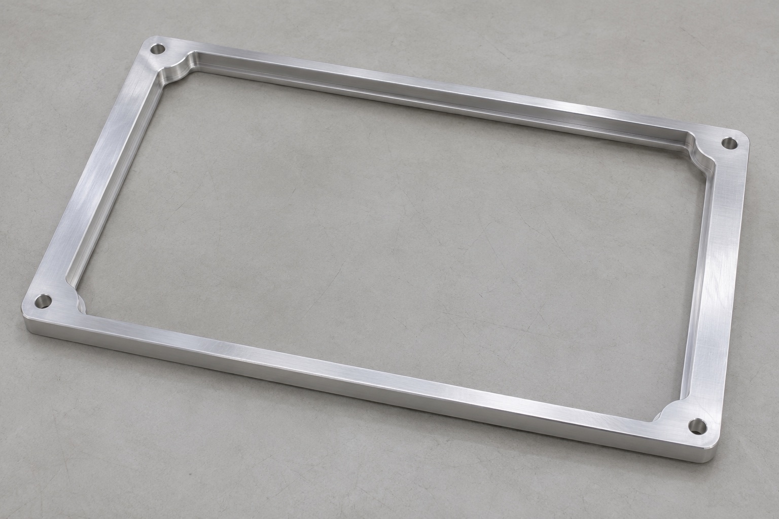
This representative case proposes a 6061 aluminum bezel for a diagnostic monitor development assembly. It has a large central opening, a shallow internal rear ledge and four corner mounting holes. The part can be evaluated with a dummy panel and chassis fixture. It is not an approved replacement for a commercial monitor and is not a record of a customer order. The proposed evidence covers geometry, agreed surface condition and an optional mechanical trial. It does not cover display output, sealing, electrical performance or suitability for use in a clinical environment.

Review panel, chassis and mounting stack
Request the frame drawing together with the panel and chassis envelopes. Identify which rear pads touch the chassis and whether the ledge supports or clears the panel. Review the front opening separately from the insert outline, including corner radii and positional limits. Confirm the hardware type and installation condition that the bench fixture should represent. If an adhesive or gasket belongs to the assembly, define its envelope and whether it is included in the trial. Mark open questions on the manufacturing review instead of selecting dimensions by fitting one unverified panel sample.
Prepare the blank and finish instructions
Choose identified 6061 stock in the condition specified on the released drawing. Record the lot before cutting blanks and check that the surface defects and available thickness allow cleanup. Agree whether the trial part is bare machined aluminum or finished, and identify which dimensions apply after any treatment. Reserve coating allowance only with an approved process. Do not infer a cleaning, optical or electrical property from the material or surface color. Protect the surfaces identified as cosmetic or functional during handling. The traveler should identify which measurements belong to intermediate and final conditions.
Establish references with broad support
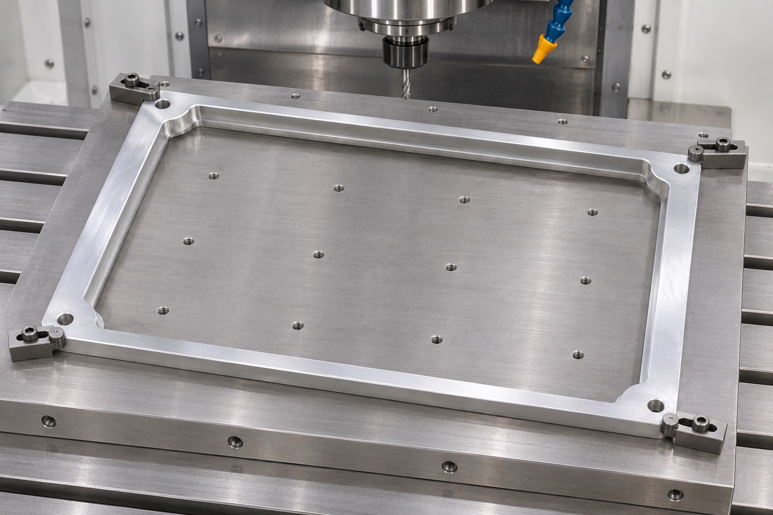
Face the rear reference and prepare the agreed lateral and end locating surfaces. Use a fixture that supports the narrow frame rails and corner pads without blocking the opening or drilling locations. Clean the underside and compare the first blank after re-seating it against the same stops. Document support and clamp locations so they can be repeated. Avoid setting critical origins from a rough stock edge that will disappear. If the rear mounting pads are finished in a later operation, establish a controlled transfer to preserve the relationship between them and the aperture.
Rough the aperture without releasing all support at once
Leave controlled finishing allowance on the aperture and ledge. If the blank loses shape as the center is removed, pause to inspect the released geometry and adjust the support or sequence before finish machining. A retained web or tabs can aid early handling if their removal is planned and does not leave raised material on a functional edge. Do not increase clamp force solely to force the blank into a flat condition. Check chip clearance and workholding as the rails become thinner. Confirm which surfaces remain accessible before choosing the orientation for final contouring.
Finish the ledge and visible opening separately
Finish the aperture from the designated datums and cut the shallow ledge to the required elevation. Keep tool reach and corner radii compatible with both surfaces. Inspect the transition in the corner pad areas where the toolpath changes direction. A single offset should not be used to correct both aperture and ledge if the measured deviations have different causes. Clear chips so they are not carried under the frame during a setup change. Record the setup sequence and inspect the first part after release, paying particular attention to the narrow sections near the long edges.
Drill the mounting holes and deburr the exits
Machine the four corner holes while the pads are supported. Check tool exit clearance and remove burrs from the rear seating surfaces within drawing limits. Verify the hole size and location before using fasteners to pull the frame against a fixture. Inspect the visible edge and ledge after deburring, because an excessive edge break can change the view opening or reduce support. Preserve the inner corners specified for the mating panel. If the cosmetic condition cannot be restored within the dimensional requirements, segregate the part and request a disposition rather than disguising the defect with polishing.
Inspect the released frame before the fit trial
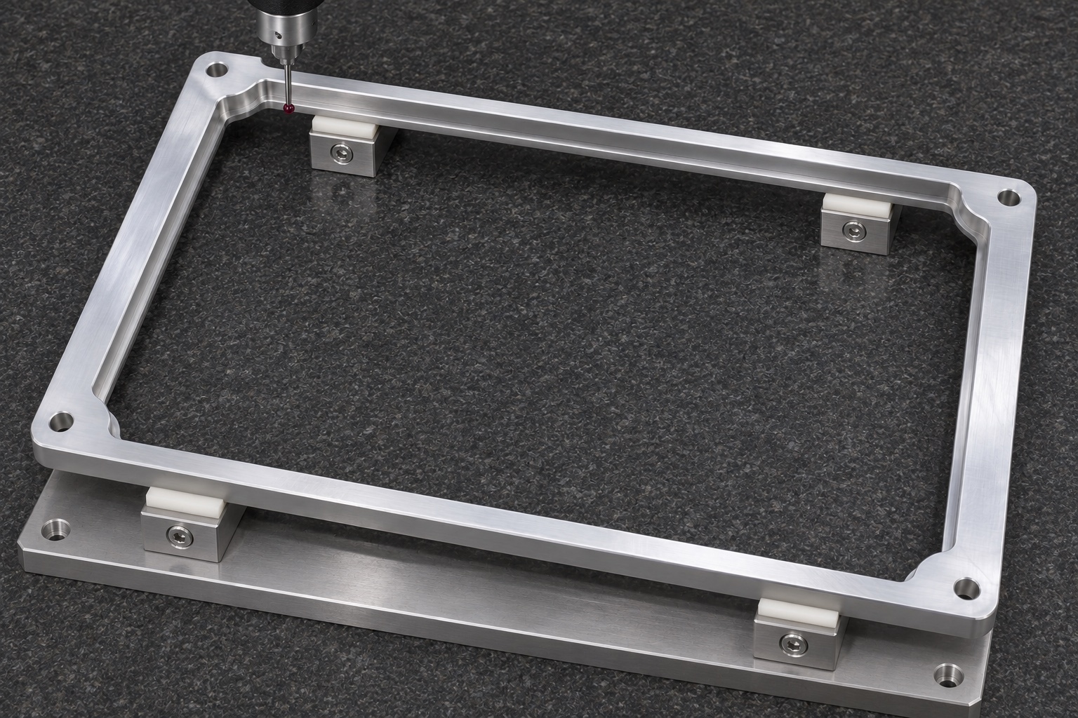
Place the bezel on the specified supports and measure the mounting surfaces without clamping it flat. Check the aperture profile at the working elevation, ledge height around the frame and the corner hole pattern. Record actual results, instrument and support configuration. If the drawing also requires a mounted check, document the fixture and hardware condition separately. Inspect the affected geometry after any specified final finish. Do not assume a dimension measured in the machining fixture represents the free-state shape. A probe that touches a fillet instead of the ledge is not measuring the required feature.
Seat the dummy panel and observe first contact
Use an inert panel surrogate representing the agreed envelope and a controlled chassis fixture. Fit the components under the approved bench condition and record whether the surrogate rests on the intended surfaces. If a fastener touches the insert or a corner blocks the view opening, identify the exact contact before proposing a change. Do not over-tighten hardware to force a fit. Record fixture and surrogate revisions, including whether the trial used only one envelope condition. This is a mechanical fit check. It does not establish performance of real glass, sealing, electrical safety or diagnostic image quality.
Trace failures to a specific interface
If the frame twists when released, compare stock condition, roughing sequence and clamp support before changing machining offsets. If it fits the chassis but the insert rocks, inspect ledge height, burrs and the surrogate rather than widening every wall. If it passes the mechanical trial but fails a required dimension, hold the part until the drawing owner resolves the disagreement. Record approved corrections and repeat affected checks. An undocumented prototype adjustment is not suitable evidence for a repeat run. Keep the actual measured data and the fixture observations separate so later revisions can be evaluated without guessing.
Define what the prototype handoff contains
Agree on stock identity, drawing revision, first-piece data, finish evidence if required and any optional fit notes. Distinguish a machining quote from a request for an inspection fixture or an assembled system test. For a repeat order, review changes in stock, clamping, tooling and surface treatment and identify which require renewed inspection. Confirm that the panel and chassis drawings remain current. This case gives a proposed route, not a completed delivery or a guarantee of monitor performance. Device-level acceptance remains with the equipment owner under a separate plan.
Prevent edge damage and bending in transit
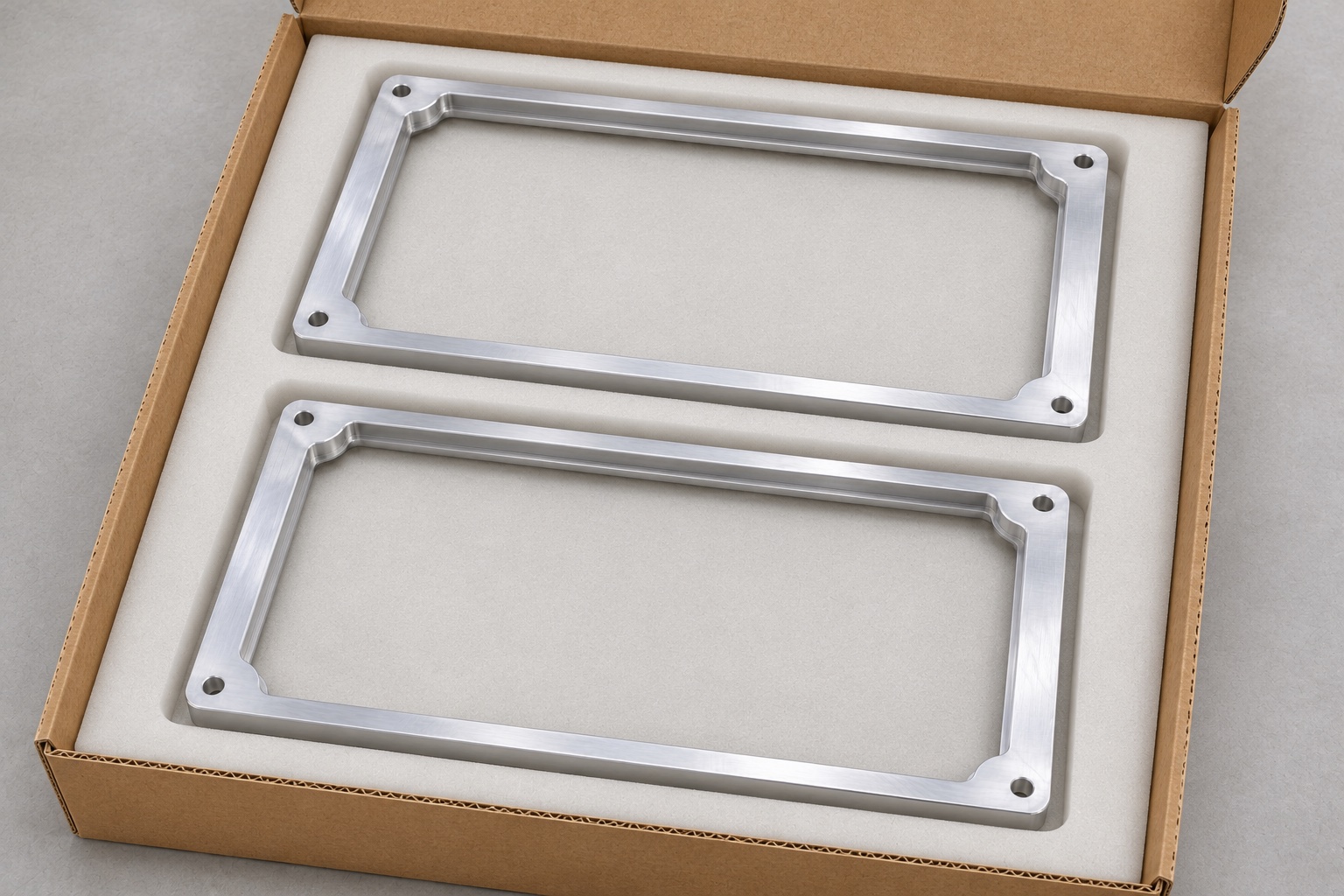
Package the bezel on a straight support with nonabrasive protection around the corner pads and long sides. Separate frames so no metal edge contacts a visible face or working ledge. Keep adhesive and loose filler out of the aperture and mounting holes. Identify the part, revision and lot on the outside and connect them to the inspection evidence. If a defined cleanliness condition is part of the order, agree on the handling and acceptance method separately. Ordinary transit packaging protects the inspected condition but does not establish sterility or a controlled clean state.
FAQ
Is this a delivered production bezel?
No. It is a representative machining plan for a development component. It does not claim a customer, completed order or qualified monitor.
Why check both free and mounted shape?
They answer different questions. A fixture can straighten a distorted frame, while the approved installed check shows how it sits under a specified fastening condition.
What belongs on the dimensional report?
Report the specified aperture profile, ledge elevation, hole pattern and flatness or profile in the agreed condition. Include the revision and measurement setup.
Does the trial use real display glass?
The proposed trial uses a controlled inert surrogate. Handling actual glass or a complete display requires separate assembly instructions and verification.
Can an anodized prototype be judged from its color alone?
No. Appearance is only one requirement. Verify dimensions and surface criteria that apply after finishing using the approved methods.
What should a repeat order recheck?
Confirm frame and mating revisions and review changes to stock, fixtures, tools or finishing. Repeat first-piece checks where the agreed plan requires them.

tanghangyun@oemach.com