
Set a bounded prototype order
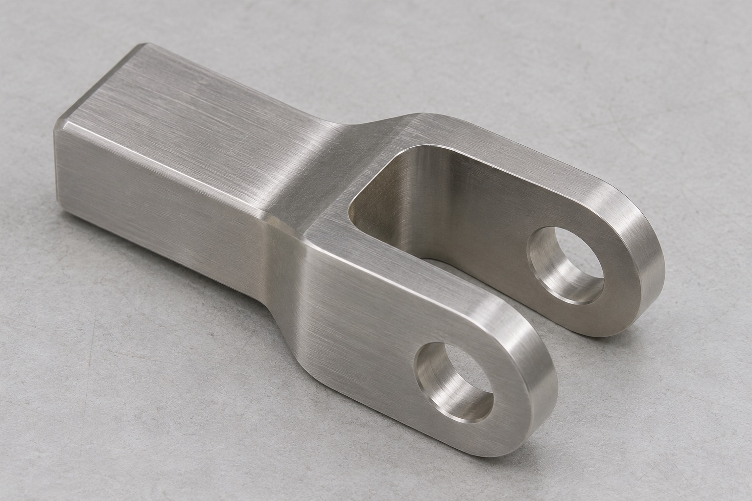
This representative machining case proposes a 316L clevis for an unpowered platelet agitator development fixture. The fork joins a drawing-controlled dummy link and pin. It consists of a rectangular shank, two parallel ears and a transverse bore through each ear. The machining order covers the fork, agreed inspection and protective packing. It does not cover the agitator, a clinical spare, the dummy link or powered motion testing. No customer delivery, device certification or measured performance is claimed. The first decision is whether the part meets the controlled mechanical drawing and whether a limited bench trial is included.

Resolve the drawing before ordering stock
Review the mounting face and side of the shank, the fork opening, the link and pin envelopes, and the intended range of the bench motion. Identify which ear faces may contact washers and whether a minimum usable bore length is needed after deburring. If the pin is retained outside the fork, note the envelope without adding a retention groove to the fork design. Record whether the supplied pin is a reference sample or an acceptance gauge. Confirm the drawing and fixture revisions separately so a prototype result can be interpreted after either changes.
Prepare the 316L blank and traveler
Select identified stainless stock in the approved condition with allowance around the fork and the shank. Mark the lot identity in the traveler before separating blanks. Review stock surfaces for defects where a finished contact face might remain. Agree on which surfaces may show fixture marks and what finishing, if any, is required. Keep these requirements independent of any device-level material decision. Document the expected handoff between roughing, finishing and inspection, especially if the order requires processing at another shop. The material name alone is not a cleaning qualification or a statement about suitability for blood contact.
Establish the shank references
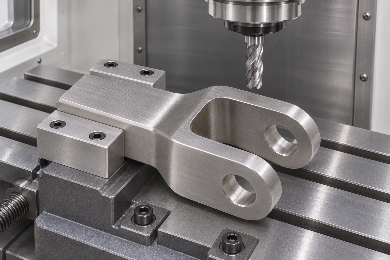
Face the shank surfaces designated as functional datums. Support the stock against a stable base and side stop and check that it seats without rocking. Keep room for the fork cutter and any fixture element that supports the ear region. Re-seat the first blank and compare its location before cutting critical features. Record where clamps act and which faces provide location. If the fork drawing uses a specific end reference, transfer it intentionally before any operation removes stock there. Cutting the outer contour from an uncontrolled saw face can otherwise move the bore position without changing the hole diameter.
Rough the open fork with support
Remove the bulk of the gap while keeping enough material for controlled finishing of the inner faces. Plan the internal corner radius and approach so the cutter does not leave an unintended step at the root. Where the material releases unevenly, inspect the part after roughing before deciding the finish sequence. Avoid a clamp that pushes the two ears together after they are thin. Finish the gap and working faces against the shank references, or document any transfer between fixtures. Inspect the released gap at the front and nearer the root, clear of chamfers and fillets.
Machine the pin passage from a common reference
Use a supported orientation that gives access along the transverse axis. In a trial route, drill both ears from the same side and finish the holes as required by the drawing. Confirm the tool can cross the interrupted space without shifting or leaving a burr that affects the next operation. A sacrificial support may be considered if it does not deflect the ears or change the required geometry. Record the approach and finish method. If the second ear is processed independently, check the datum transfer and measure the assembled envelope rather than assuming equal diameters imply one common axis.
Deburr internal exits and verify the surfaces
Inspect both inner bore edges, the external entries and the gap root. Remove burrs only within the allowed edge-break limits. A raised edge can prevent a fit trial from diagnosing actual bore alignment. Use a method that reaches the hidden exit without scratching the wall or enlarging the bore. Reinspect any edge touched during manual work. If material remains outside the approved limits, hold the part rather than blending the entire contact surface. Record the location of the defect and the disposition. The finished fork should remain distinguishable from rough samples in the lot and packaging.
Separate the bore and gap results on the report
Measure both bores from the released shank references and report the applicable position or axis relationship. Check the gap at the working sections and document the method and support condition. A separate pin-passage check can be recorded at the stated insertion direction and force. Check the measuring instrument can reach the actual cylindrical surfaces without contacting an edge break. If the drawing calls for a particular surface treatment, verify the relevant dimensions in their final condition. Record actual readings and the instrument used instead of a general acceptance statement. Missing probe access must be resolved before releasing a result.
Use an unloaded link trial to identify interference
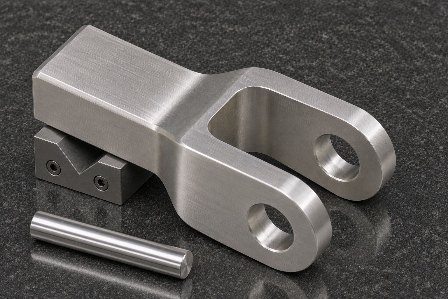
With the fork seated in a bench fixture, introduce the approved pin and dummy link without force beyond the agreed test limit. Check whether the link moves within the specified trial span and where it touches first. Report the fixture, link and pin revisions. A successful hand trial does not represent a powered agitator or establish any operational performance. Do not test with specimens or real storage equipment under this component plan. If the trial reveals interference, keep the dimensional results and trial observations separate so the cause can be assigned to a specific part or mating feature.
Diagnose what changes before correcting it
If the pin stops after crossing the first ear, inspect both internal exits and compare the bore locations. If it enters fully but the link rubs, check the gap, link width and root radius before enlarging the holes. Check clamp force and shank seating if readings vary after reseating. Segregate affected parts and follow the drawing owner's decision process for any deviation. Record what changed and which features were reinspected. An accepted adjustment on one prototype does not automatically become the repeat machining method. Update the traveler and approval evidence before treating that adjustment as part of a new lot.
Define the evidence for a repeat order
The proposed delivery evidence includes the current drawing revision, material identification, measured results and any limited fit-trial notes. Quote a dedicated inspection fixture or special surface treatment as separate items. Review changes to the pin, shank support, stock or finishing before repeat production. Agree which changes require renewed first-piece approval. The prototype report is not process capability data and should not be used to claim a customer result. Its value is to make the next review reproducible, with the measured characteristics, reference conditions and unresolved equipment-level tests explicitly identified for the responsible owner.
Pack the fork without bending the ears
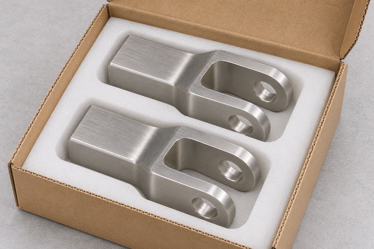
Place each part in a separate protective pocket supporting the shank or approved outside surfaces. Keep pressure off the ear tips and prevent the mating pin from rubbing the bores during transport. Use external labels with the revision and lot, and retain the link to the inspection package. Do not put loose filler or adhesive into the fork gap. Inspect the condition of the working edges at receipt. The proposed packing is ordinary transit protection, not a sterile system. Define any additional cleaning, particle control or handling requirement in a separate specification before the order is released.
FAQ
Is this a delivered customer component?
No. This is a representative route for a bench fixture clevis. It does not claim an actual order, a certified device part or a measured production outcome.
Why hold the fork by the shank?
The shank offers a stable mounting reference without deliberately pressing the ears together. Confirm the chosen setup and inspect the released geometry.
Can both ears be checked with only a pin?
A controlled pin checks passage. Individual bore geometry and the axis relationship to the shank need separate inspection when required by the drawing.
What should happen if the pin binds?
Record where it stops. Check burrs, reference alignment and the relevant bore geometry before proposing rework; do not force the pin through.
Is any powered equipment testing included?
No. The optional trial is unpowered and unloaded. Operational validation and equipment authorization remain outside the proposed component order.
How is the prototype protected in shipment?
Separate parts in individual pockets and support approved surfaces rather than the ear tips. Keep debris out of the bores and link packaging identity to inspection records.

tanghangyun@oemach.com