
Set boundaries for the prototype gauge
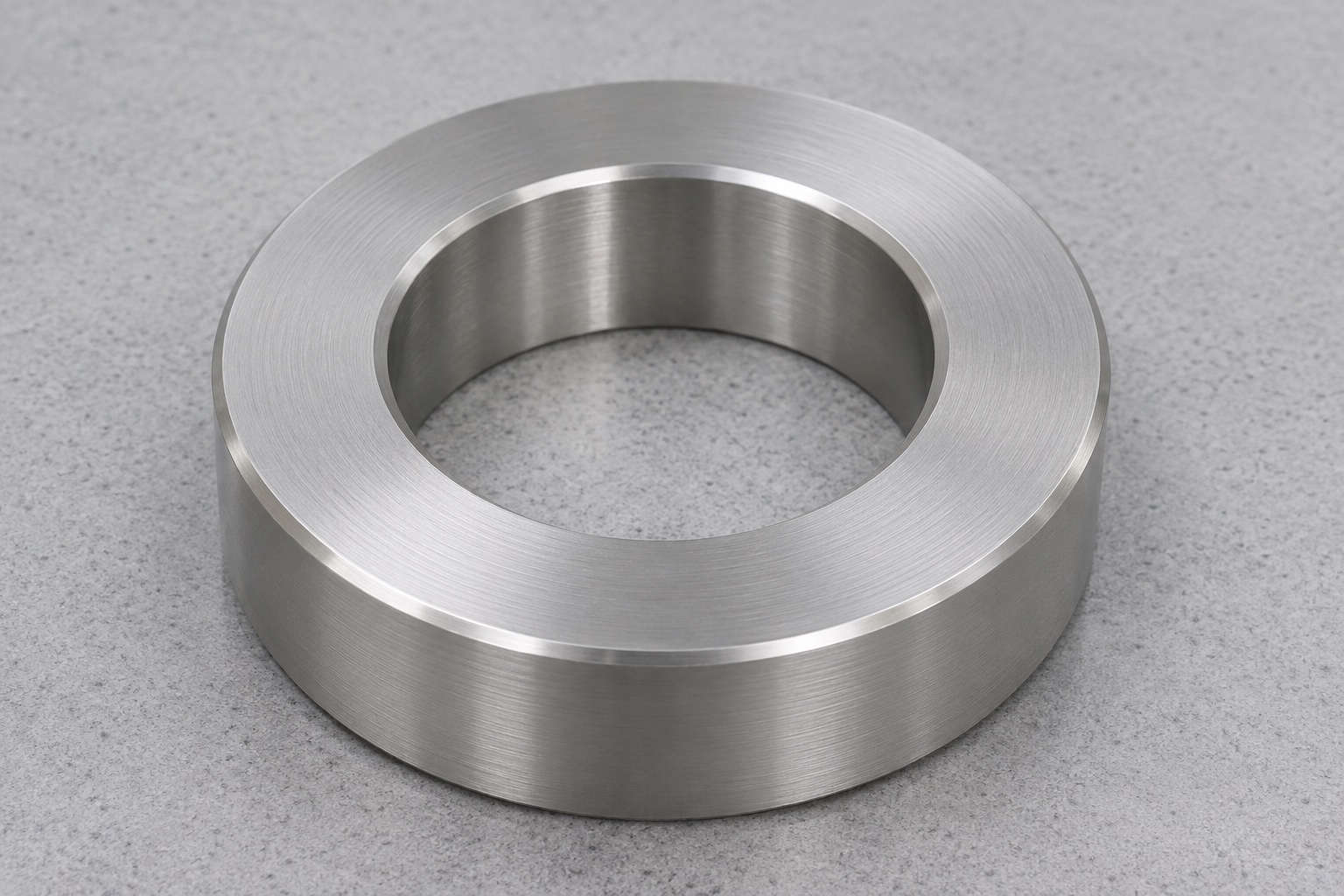
This representative manufacturing case proposes a 316L bench inspection ring for a generic surgical light handle drawing. The ring has a straight through bore, two flat faces and a controlled entry chamfer. It would help decide whether a defined cylindrical section can enter under an approved method. No customer order, commercial spare or completed gauge calibration is claimed. The tool is not installed on the light and has no patient-facing role. The case covers a proposed route for turning, inspecting and protecting the ring, with system-level handle testing explicitly excluded.

Review the workpiece and gauge drawings together
Request the handle revision, checked length, limit and intended insertion direction. Check whether a rib or shoulder can reach the ring before the cylindrical section. The gauge drawing should define the working bore, permitted form, effective length and faces that position the ring. Confirm whether an entry on both sides is required. Agree how the fit decision will be made and what master or measurement is expected before use. A ring bore cannot be selected from a nominal handle size alone. Document the gauge limit and verification rule separately from the dimensions of the production handle.
Prepare traceable material and cleanup allowance
The proposed route uses identified 316L stock. Select a round blank with enough allowance for the outside diameter, faces and bore; an existing opening is acceptable only if sufficient material remains around it to clean up. Transfer the material identification to the traveler. Inspect the stock where discontinuities might intersect a working surface. Confirm whether the buyer requires any treatment, surface finish or material documentation. Do not infer hardness or service life from the alloy name. If the duty or wear expectation changes, review the material selection and gauge verification plan with the responsible quality owner.
Face and bore in the primary setup
Locate and support the blank without forcing it into a distorted shape. Face the exposed annulus, rough the opening and leave a consistent allowance for finish boring. Finish the first face and working bore in the same setup where the drawing calls for their relationship. Check insert condition, bar reach and chip evacuation before changing offsets. A rough bore may be tapered even when the entrance reads near target. Confirm that the final cut cleans up the full working length. Record setup conditions that affect repeatability, rather than assuming a machine program alone establishes the bore geometry.

Reverse the part without using the bore as an uncontrolled grip
Use a suitable collet or bored soft jaws on the outside diameter if permitted by the drawing. Seat the completed face against a clean stop and check that the part does not rock. Finish the rear face and remaining entry feature with enough support to avoid deflection. Do not press an expanding fixture into the working bore unless the process is approved and shown not to damage or distort it. Check thickness and the required face relationship after release. If the ring will rest in a fixture, inspect the actual supporting surface rather than an unrelated cosmetic rim.
Inspect the entry and working surface before any trial
Verify chamfer size and working length before trying a master or handle surrogate. Inspect the bore for chips, burrs, scoring and raised edges using the agreed visual method. Do not remove a burr by repeatedly forcing a reference part through it. A hand-blended entry that reaches too far into the bore can make the gauge less useful without noticeably changing the largest diameter. Any correction should stay within the approved drawing. Reinspect affected features after deburring or treatment, and keep the ring separate from ordinary washers or unverified blanks with a similar appearance.
Measure the finished ring under controlled conditions
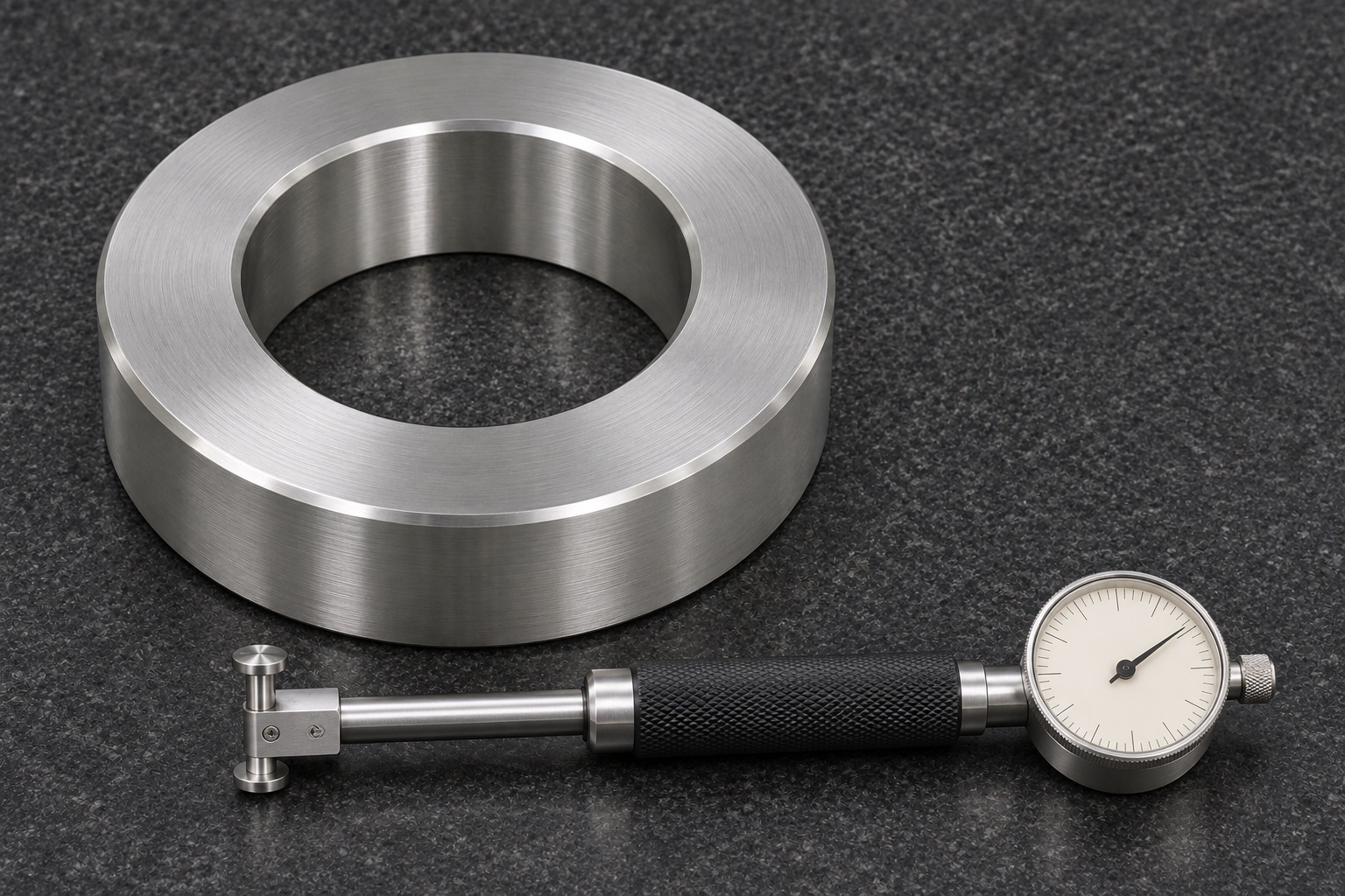
Use a suitable calibrated internal measurement system and the specified reference. Inspect the bore at the drawing locations, including multiple depths and orientations where necessary. Check geometric form separately if specified, and document how the result was determined. Record the instrument, ambient or conditioning requirements, uncertainty where needed and actual readings. Consider a second verification method if the result is too close to a decision boundary for the instrument. A traceable report should say what was measured, not simply list a bore value without describing the zone or condition.
Trial the method with an approved reference
Use a designated master or surrogate appropriate to the defined check. Follow the approved direction, depth and force limit, with both surfaces free of loose material. Observe where contact occurs and record the fixture conditions. Do not use a production handle that happens to fit as proof the ring is correct. If the buyer commissions formal calibration or method qualification, treat it as a separate deliverable with its own acceptance. This proposal contains no actual measured bore values or verification results. It describes how evidence would be collected for the next decision.
Investigate a mismatch before touching the bore
If a verified reference stops at the entrance, inspect the chamfer and any burr first. If it enters partway and binds deeper, compare bore size, taper and alignment at the relevant sections. Check that reference, temperature and support match the procedure. If repeated readings suggest lobing after unclamping, revisit workholding before changing the tool offset. Hold the affected ring and confirm the permitted disposition before reworking the working surface. A useful record links the observed mismatch, corrective action and reinspection. A label should not be used to conceal that a ring is pending verification.
Identify the ring and its verification status
Specify identification on a nonworking surface or on the dedicated container. Tie the identifier to drawing revision, material lot, actual measurements and any approved verification status. When engraving is required, check that its location and method do not distort the ring or raise material near the seating face. For repeat orders, confirm that the handle revision and decision rule are unchanged. Identify process changes that trigger a renewed check. The commercial quote should separate the machined blank, measured gauge, fixture and verification services so no party assumes that calibration is included when it is not.
Protect the gauge in storage and shipment
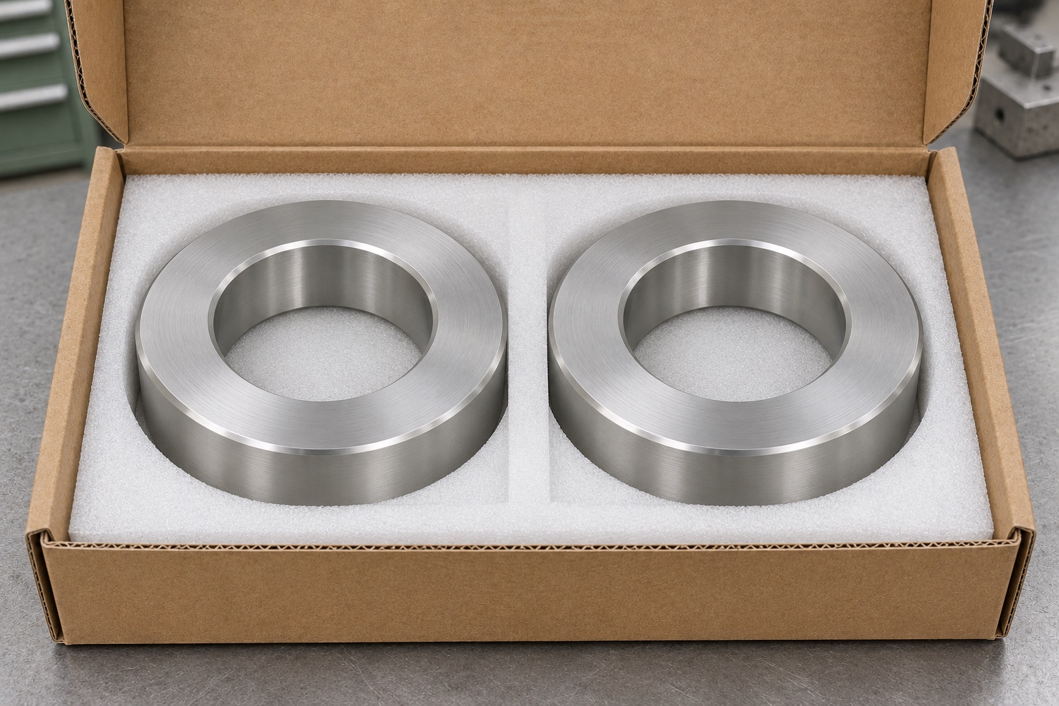
Use a divided or individual container that supports the outer body without rubbing the working bore. Avoid packing material or tape inside the opening. Keep metal-to-metal contact away from the measuring faces, and include handling instructions if agreed. Put the identifier and drawing revision on the outer package, with the inspection evidence kept accessible separately. Inspect for damage at receipt before first use. The ordinary protective package is not a sterile barrier. The inspection ring should remain a bench tool, with periodic checks and withdrawal criteria defined by the buyer's gauge control procedure.
Define the handoff before production use
The proposed handoff includes a released gauge drawing, specified material evidence, dimensional results, any additional verification and a documented acceptance procedure. It should state which area of the handle the ring checks and the response to an ambiguous result. A later change in material, finishing route or gauge supplier can require review even if the shape stays the same. The final equipment manufacturer remains responsible for approved assembly and device validation. Nothing in this representative case claims that a customer received the ring, that the gauge is certified or that a surgical light passed a test.
FAQ
Is this an approved spare part for a surgical light?
No. It is a proposed bench inspection tool for a drawing-controlled handle, not part of a commercial light assembly.
Why finish the face and bore together?
It can preserve the intended reference relationship. The second setup and released inspection must still confirm the relevant geometry.
Does the first-piece report count as calibration?
Only if the contracted procedure, reference and required evidence establish that deliverable. A general dimensional report should not be relabeled as calibration.
What if the bore seems tight only after reclamping?
Compare the released and restrained conditions and inspect the workholding. Clamp pressure can temporarily change ring shape.
Where should the ring be marked?
Use a drawing-approved nonworking location or identify the dedicated container. Keep the working bore and seating faces free of raised marks.
Can a fit trial demonstrate handle retention?
No. It addresses only the envelope and conditions represented by the trial. Retention and equipment performance need separate evaluation.

tanghangyun@oemach.com