
Frame the request as a mechanical prototype
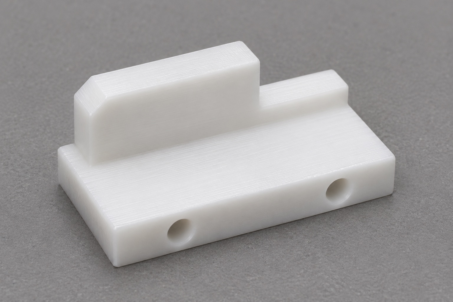
This representative machining case concerns a POM-C orientation key for a generic automated sample tube rack. It does not describe a customer order, a commercial replacement or a successful instrument test. The part has a flat rectangular base, two cross holes, and a raised stepped tongue with a short chamfer at one end. A drawing-controlled bracket carries the key. In the intended orientation the rack clears the tongue; in reverse a defined shoulder interferes before full seating. The proposed prototype scope covers manufacturing and agreed component checks, not automated sample identification or motion control.

Record both approach conditions in the drawing review
Request the bracket and rack envelopes, including the surfaces that locate the key and the clearance features in the rack. Mark which end must enter first. Add a section view or fixture sketch for the reverse trial to show what feature should block travel and how much seating distance must remain. Do not use a convenient sample as the only source of limits unless it is accepted and documented as a gauge. The design review should resolve whether the key is adjusted during assembly or sits against fixed locators. That choice affects how the cross holes are interpreted.
Prepare traceable stock and trial blanks
Select natural POM-C stock that meets the released specification. Keep the material identity with the cut blanks and record the thickness available for the base and tongue. Examine the blank for visible damage near working surfaces. Color does not establish grade, conditioning or chemical compatibility. If the drawing has a required measurement temperature or stabilization period, make it part of the traveler. Use the first blanks to evaluate setup and edge behavior before releasing a repeat lot. Record changes to stock source or condition when they may affect the measured geometry.
Establish a base that does not rock
Face the underside and machine a side reference suitable for the later tongue setup. Use a broad, clean support and light controlled clamping rather than forcing a bowed blank flat. Verify the reference surfaces after releasing and reseating the first blank. Keep chips from lodging beneath it. If a blank moves after roughing, review support, stock condition and removal sequence before adding clamp force. Set the machining origin from the documented locating surfaces rather than a raw edge. The eventual inspection fixture should recreate the same functional reference system without imposing the machining restraint.
Mill the asymmetric profile in a controlled setup
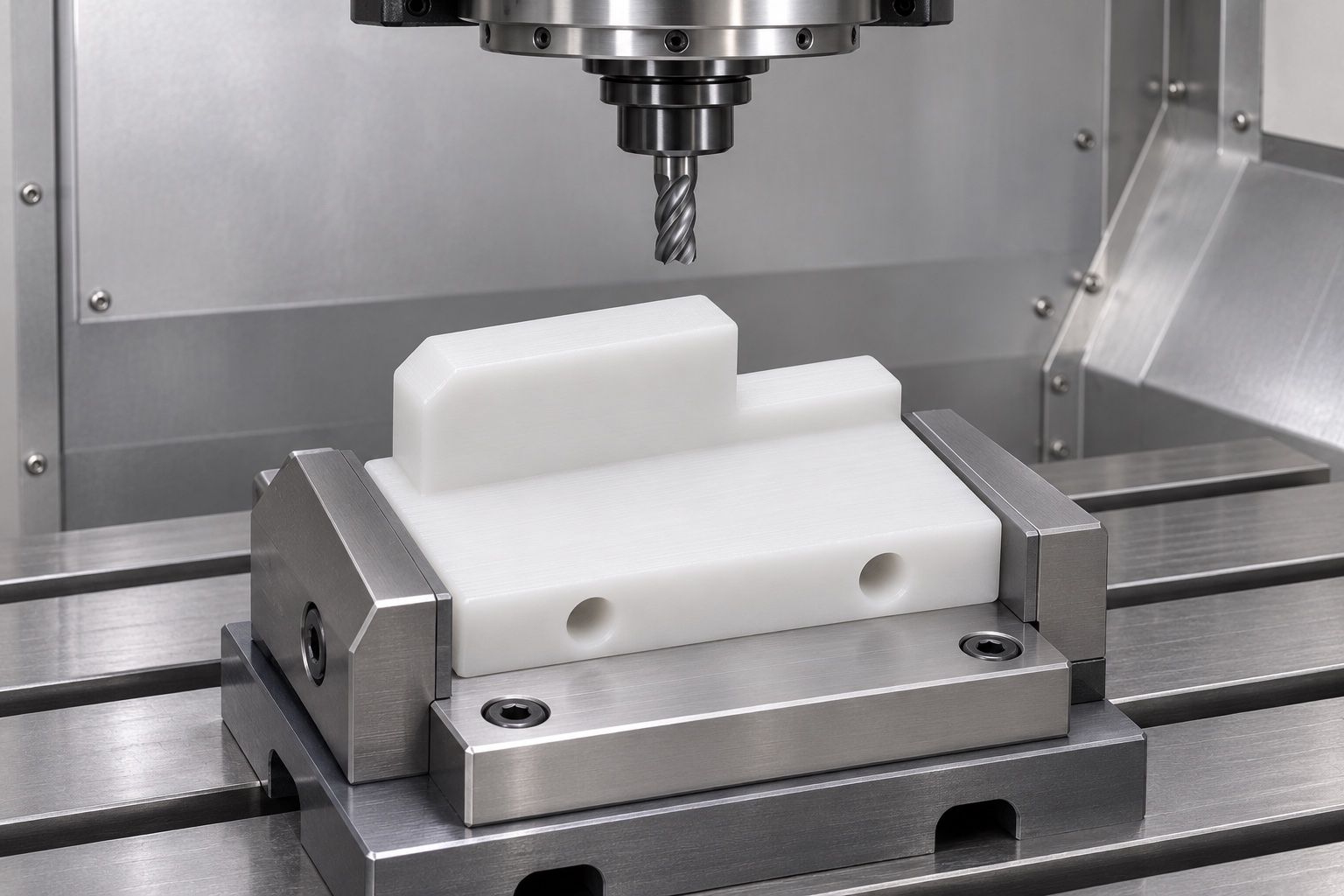
Rough the high and low sections of the tongue with a stable finishing allowance. Finish the working flanks and the defined blocking shoulder from the base and side references. Leave the lead-in to a controlled operation so its start and end are visible on the first-piece check. Keep enough support beneath the base to avoid deflection while cutting near the step. Inspect the edge and surface after the first part is released. If the profile has a raised lip, establish whether the issue is tool condition, chip evacuation or deformation rather than treating it as a dimensional offset.
Cross drill from transferred datums
Reorient the blank in a supported fixture for the two side holes. Locate it from the same base and side references or use a documented transfer. Confirm tool clearance at the exit so a sacrificial backing or fixture does not become an unintended stop. Inspect diameter and position according to the drawing, and check that the exits are free from burrs that could prevent seating or interfere with screws. Do not use the completed tongue as a clamp pad. Record the fixture orientation so the two holes cannot be accidentally drilled from the wrong face on a repeat lot.
Preserve the step during deburring
Remove only the edge material allowed by the drawing. Inspect the transition from the lead-in to the blocking face, where excessive blending could let the reversed rack travel farther than expected. Clear chips from the holes without scraping the working sides of the tongue. Where visual criteria apply, agree on viewing conditions and example defects. Repeat the relevant profile check if deburring touches a controlled surface. If a burr cannot be removed within the specified limit, segregate the part and ask for a disposition rather than rounding the entire step by hand.
Check free-state profile and mounting geometry
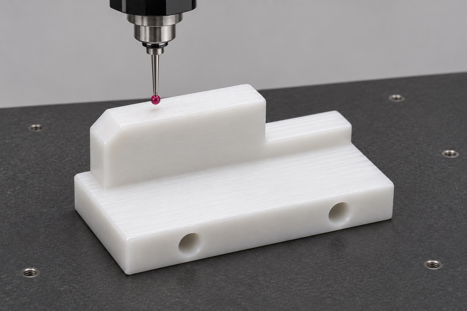
After unloading, measure the base and tongue on the agreed supports. Check the high and low portions, the shoulder location and the chamfer profile independently. A contact instrument needs a suitable probe force for the plastic; a vision method needs adequate contrast and a defined edge. Inspect cross-hole dimensions and report the setup used. Record actual readings, material identity and revision rather than a generic acceptance statement. If measurements differ after reseating, examine the support and the part's free-state condition before changing offsets. The report should identify any feature not reached by the selected instrument.
Verify correct and reversed entry on the bench
Use a clean rack surrogate and bracket fixture made to the agreed geometry. In the permitted direction, approach the key and observe whether the surrogate seats at the defined face. In reverse, observe whether it meets the intended blocking shoulder before reaching the seat, without exceeding the agreed trial force. Record the fixture revision, approach and first contact. A successful observation on one fixture does not establish behavior across every rack variant or automated operating condition. The responsible equipment owner defines any instrument interlock, handling or traceability verification.
Diagnose a failed trial before changing the shape
If both orientations bind, look for fixture misalignment, trapped chips or unintended contact at the base before modifying the tongue. If forward entry works but the reversed surrogate reaches the seat, examine the step position and chamfer against the drawing and verify that the trial uses the correct revision. Record the issue and segregate affected parts. Only adjust the design or accept a deviation through the agreed approval process. This prevents an informal prototype adjustment from turning into an undocumented production feature that cannot be inspected on the next lot.
Make the handoff useful for a repeat order
Provide the current drawing, stock identification, first-piece evidence and separate fit trial notes as agreed. Identify which process changes require a renewed first-piece check. For a supplier quote, separate the key, fixture, inspection and packaging so the scope is explicit. A replacement rack revision may change the acceptance checks even if the key drawing remains unchanged. Review both interfaces before repeating the order. The proposed machining evidence does not include service-life, regulatory or instrument performance claims, and the case reports no measured results from an actual production run.
Prevent damage to the raised tongue in transit
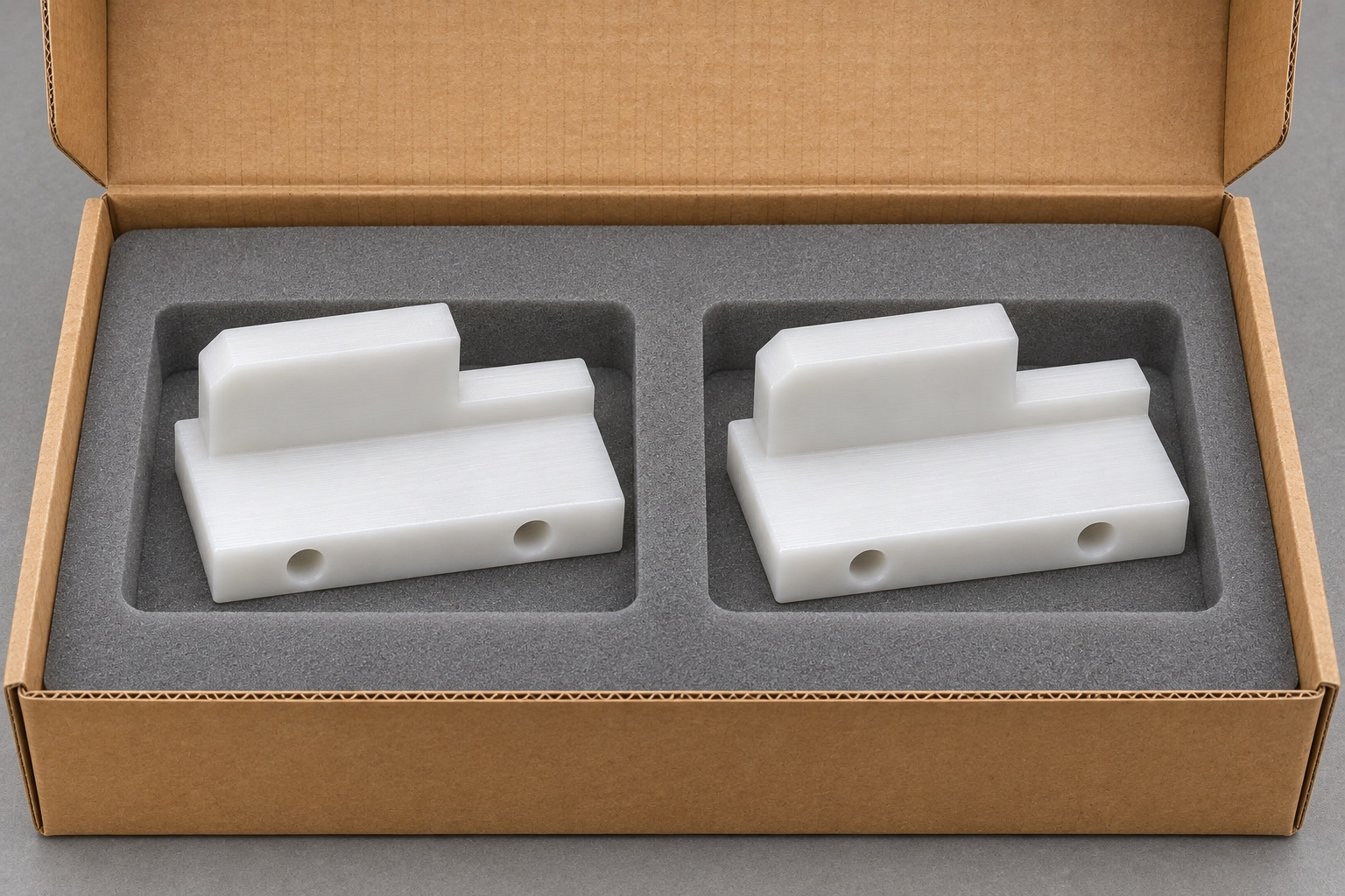
Use individual pockets that carry the base and keep neighboring parts away from the step. Avoid pressure from a lid or wrap that may bend the thin tongue. Keep loose filler and adhesive out of the holes and around the lead-in. Mark the package with part identity, revision and lot, and link it to the inspection documents. If first-piece samples travel separately, preserve their identity. The proposed package is ordinary protective packaging, not a sterile barrier. Controlled particulate or cleaning requirements must be defined and verified separately if they apply.
FAQ
Is this an actual customer case?
No. It is a representative route for a drawing-controlled key, without a customer, verified delivery or claimed production result.
Why drill the holes in a second setup?
Their axis is transverse to the top milling direction. A supported secondary setup can provide access while preserving the reference relationship through controlled locating features.
Which surface rejects the reversed rack?
The specified blocking shoulder, not an accidental burr or the screw heads. Confirm the intended contact in the drawing and use a separate reverse fit trial.
Can the drawing omit the chamfer limit?
That would leave an important feature open to interpretation. Limit the lead-in so it helps entry without removing the blocking face required in reverse.
Does an accepted key verify sample identification?
No. It addresses a mechanical condition. Identification, sensing and automated handling remain system-level functions requiring their own verification.
What does the prototype package contain?
The agreed drawing, material identity, actual inspection results, any fixture observations and lot packaging records. This example describes the proposed evidence, not results from a completed lot.
tanghangyun@oemach.com