
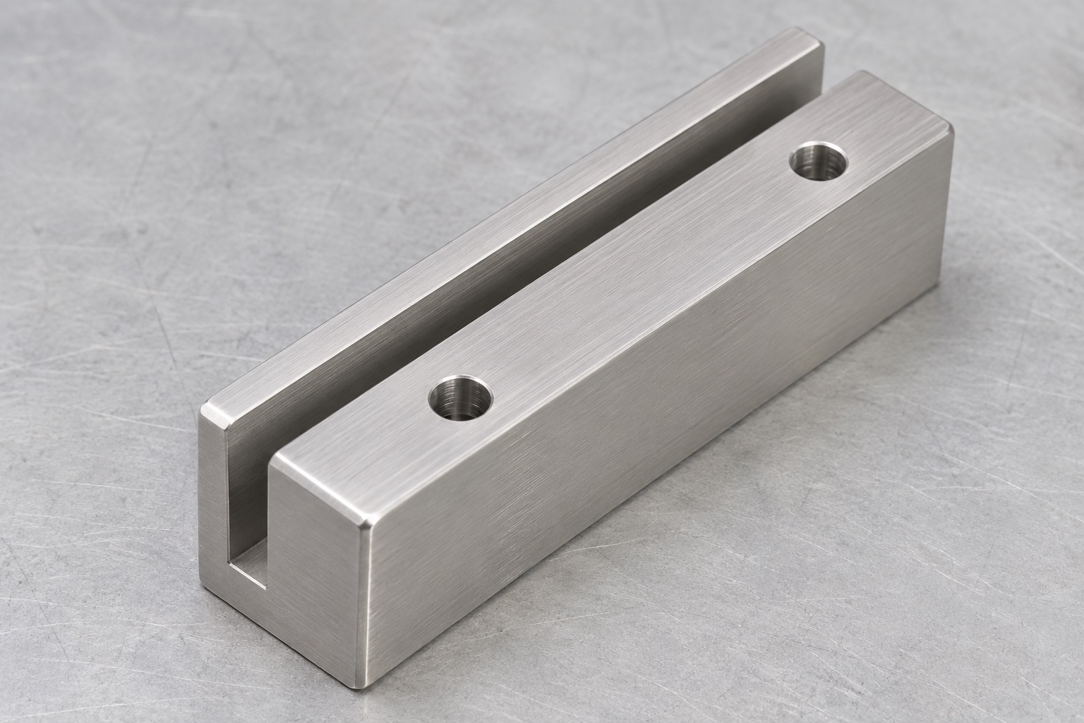
A prototype scope with clear limits
This representative machining case describes a proposed 316L edge mounting block for a pathology grossing workstation splash shield. It is not an actual customer delivery or a replacement for a named workstation. The part is a rectangular block with an open-ended lengthwise slot and two clearance holes in its wider side. The slot carries a defined panel edge; the clearance holes attach the base to a support. The example order covers machining, inspection and packaging of the block. Panel retention, workstation integration and protective effectiveness are outside the proposed component trial.

Review the intended insertion path
Start with the drawing and section view of the panel edge. Review how the panel reaches the slot, how deep it seats and what limits lateral movement. Identify any radius, liner or coating on the part that enters the opening. If two blocks are used along one edge, check the dimensional stack between them and the support rather than treating each block in isolation. Before quoting, record whether a rectangular coupon will be supplied and which edge condition it represents. Do not infer clearance from the drawing of a nominal panel alone.
Confirm incoming material and the finished state
The route begins with identified 316L stainless stock sized to allow cleanup on the base and the wider cheek. Transfer stock identification to the production traveler before cutting blanks. Inspect the raw stock for damage where material may remain near the final slot or bottom surface. If the order requires a specific finish, record whether the final dimensions are evaluated after that operation. Reserve any allowance only through an approved process plan. A material record can support traceability; it does not certify a finished part for a particular exposure or procedure.
Prepare a stable base and side reference
Mill the underside and one long outside face so the blank seats reproducibly in a fixture. Check that the faces are free of burrs before they become working references. Use a stop on a suitable end face to set the origin for the slot and mounting pattern. Re-seat the first blank to confirm that the locator and supports repeat. Where the blank overhangs the fixture, support it without deflecting it into position. Document which surfaces are accessible during the next operation. Repeatedly setting the origin from a sawed edge would add variation unrelated to the actual mounting datums.
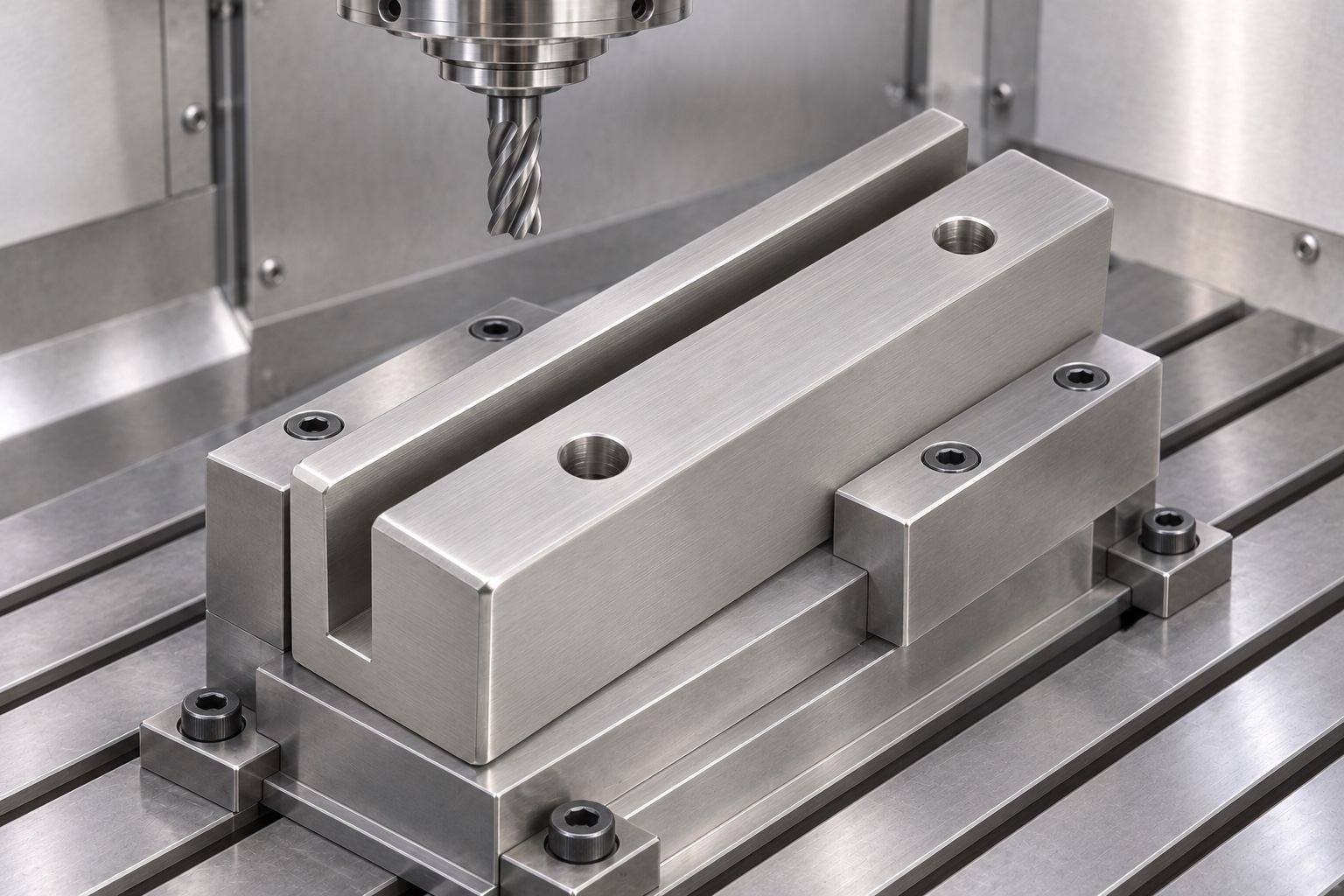
Rough and finish the open channel
Rough the lengthwise channel while the block is supported along its base. Leave a consistent finish allowance on both walls where the toolpath permits, then finish the working width and floor from the same references. Pay attention to chip recutting near the bottom and cutter deflection through the full depth. Avoid moving the origin based only on a measurement at the mouth. On the first part, compare the released width near both ends and the center. If the results disagree, investigate cutter reach, fixture pressure and edge buildup before making a blanket size correction.
Drill the attachment pattern without distorting the cheek
Machine the two drawing-controlled holes in the wider cheek, using a setup that leaves the drill exit clear and supports the part. Keep the channel free from chips and raised edges during handling. Check hole diameter and location independently of channel width, since the holes are intended for fastener clearance. On the underside, confirm that the drill breakout does not leave a ridge on the seating plane. Verify the planned fastener and tool envelope if it is included in the drawing. A successful screw insertion is not an acceptance check for preload or structural retention.
Finish and deburr without rounding the seating land
Deburr the channel entry and the two open ends to the allowed drawing limits. An excessive edge break can reduce the supported edge length, particularly if the liner engages only a short section. Check the wall-to-floor corners for burrs and any unintended radius that could prevent full insertion. Use visual inspection with the agreed lighting and magnification where needed. If the work requires subsequent surface treatment, protect the mating surfaces during transfer and repeat checks affected by the process. Do not grind or hand blend a functional surface beyond its specified limits.
Record actual channel measurements
Inspect the slot and base after releasing the workpiece, using a setup that does not press the cheeks inward. Measure width at agreed depths along the slot and record depth from the designated reference. Verify the attachment pattern and seating surface independently. Identify the instrument, drawing revision and support condition on the report. If a gauge cannot reach a narrow corner, record the limitation and agree on a suitable method instead of assuming the unmeasured surface conforms. First-piece approval is an agreed decision, not an automatic result of reaching the nominal dimension once.
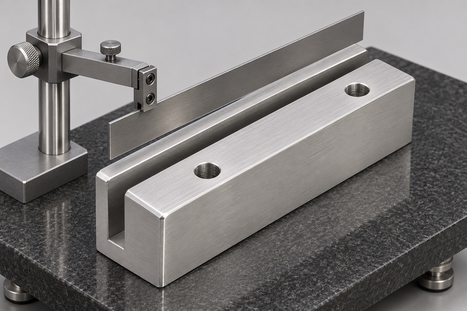
Try the drawing-controlled coupon on the bench
Insert a nonclinical coupon representing the actual panel edge, including any intended liner if specified. Observe initial entry, steady engagement and seating. If two blocks are involved, use a controlled support to verify that the slot positions are consistent with the assembly drawing. Keep the trial unloaded except for the defined insertion condition; do not apply impact or retention loads in a fit check. Record the coupon and fixture revisions and how the check was performed. The evidence applies to that mechanical fit only, not splash protection, fume control, cleaning or workstation safety.
Investigate local interference before reworking a lot
If the coupon binds at the middle, compare measured width and straightness there against the ends. Look for a local burr or burr roll-in before removing stock from both walls. If the block rocks on the support, inspect burrs at the hole exits, debris and base flatness before deepening the channel. Segregate the affected pieces and obtain approval for any correction that changes the drawing condition. A meaningful process record links the observed defect to the operation, the approved corrective action and the resulting reinspection, rather than listing only the final pass or fail.
Define the repeat-order evidence
For a prototype order, agree on the released drawing, material documentation, measured results and any limited fit-trial notes. On a repeat lot, identify changes in stock, cutter, fixture or finishing route that trigger a renewed first-piece review. Keep the part and mating sample revisions aligned. If a coating, cleaning or packaging requirement is unresolved, list it as an open item in the quote and do not substitute a generic claim. This keeps the custom CNC milling scope tied to the component rather than implying a finished, qualified workstation assembly.
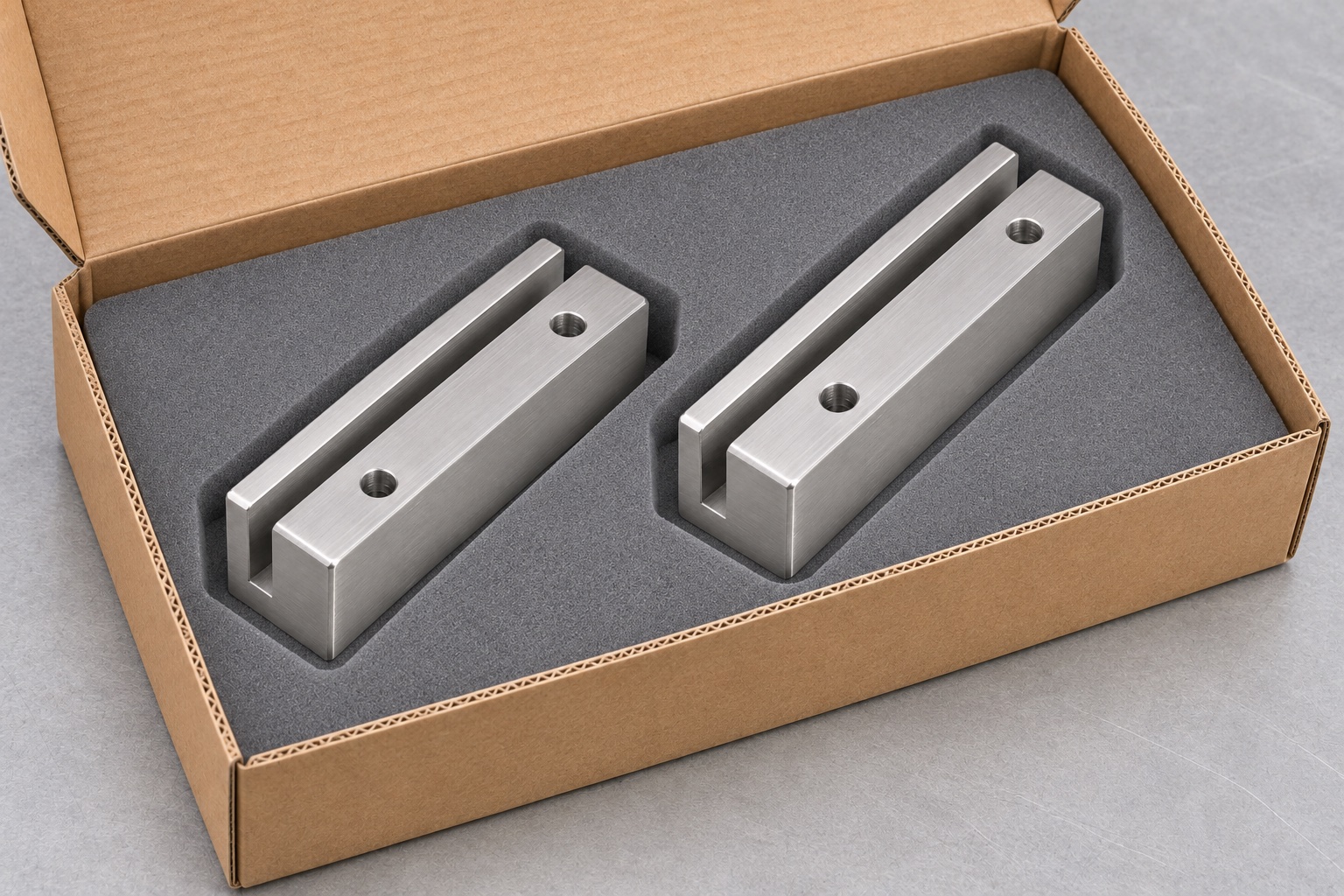
Package without contact between machined channels
Use individual protection or a divided tray so adjacent parts cannot strike a slot wall or scratch the base. Avoid adhesive or loose filler inside the channel. Identify the order, revision and material lot on the packaging, and retain the link to the inspection report. If the first piece is packed separately, preserve its identity and the handling condition expected at receipt. This example uses ordinary nonsterile protective packaging. Any controlled cleanliness requirement needs explicit acceptance criteria and an agreed handling plan before the order is released.
FAQ
Why place the mounting holes on the wider side?
In this representative drawing, that location separates attachment from the panel slot. Edge distances, thread engagement in the support and mechanical loads still belong to the assembly design.
Is a successful panel trial a strength test?
No. It checks entry and seating under stated conditions. Retention, impact behavior and protective performance require separate evaluation of the complete assembly.
Where should the slot width be measured?
Use the agreed locations and depths below the entry chamfer. Report the points and method so the measurements can be repeated and related to the working panel edge.
Can the stock finish be accepted as the finished surface?
Only if it meets the drawing and purchase requirements. Record any required finishing and inspect the affected geometry in the specified final condition.
Is this an example of an actual delivered order?
No. It is a representative manufacturing example and does not claim a customer, completed shipment, certification or measured production result.
What must be agreed before ordering another lot?
Confirm the current drawings, stock and finish, inspection scope and any renewed first-piece triggers. Recheck the panel and support interfaces if either revision has changed.

tanghangyun@oemach.com