
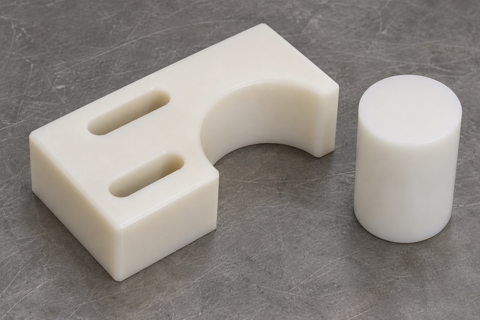
Define the hypothetical component
This representative machining example concerns a natural POM-C guide shoe with one open concave wall and two elongated mounting slots. It is not an actual order, approved spare part or record of a validated labeling process. The proposed part would be accepted against a controlled drawing and an inert container envelope. The case addresses support during milling, slot travel and arc inspection. It includes hypothetical troubleshooting examples rather than measured results. No medication, active machine, barcode data or clinical workflow is involved. The equipment owner would approve the contact and adjustment requirements before any manufacturing release.

Agree on the two references
The example assumes a broad lower plane that seats against an approved plate. A separate setup feature establishes the profile origin; the slots permit adjustment. Request the mating plate and container-envelope drawings, including the expected contact height and travel direction. Confirm whether the shoe rests on the entire plane or only on named pads. A blank with a clean outside edge may still sit incorrectly on raised material at a slot exit. The machining and inspection routes should use the same functional relationships. If the equipment owner has not defined the adjustment position, document that issue before accepting a fit check.
Match the stock to the material requirement
Choose the drawing-approved POM-C stock with sufficient allowance for the lower plane, slots and concave cut. Link the blank to the stock record and preserve identification through the operation sequence. A similar polymer is not a substitute simply because it can be milled with the same tool. Consider stock history and the amount of asymmetric removal around the open arc. The example does not prescribe a universal conditioning period or machining parameter. Where dimensional stability is critical, the controlled process should specify when the released part is measured and how its condition is recorded.
First operation: prepare a supported reference
Support the rough blank on a stable surface and establish accessible reference faces. Locate it without squeezing the thin regions that will remain near the concave wall. Retain enough blank material for positive restraint during slot and profile roughing. Inspect the seat for chips or fixture marks before relying on it. Record the orientation and support points that will carry into the second operation. If the blank cannot be held without forcing it flat, revise the support plan. A flat reading under a clamp does not establish the form that will be measured after release.
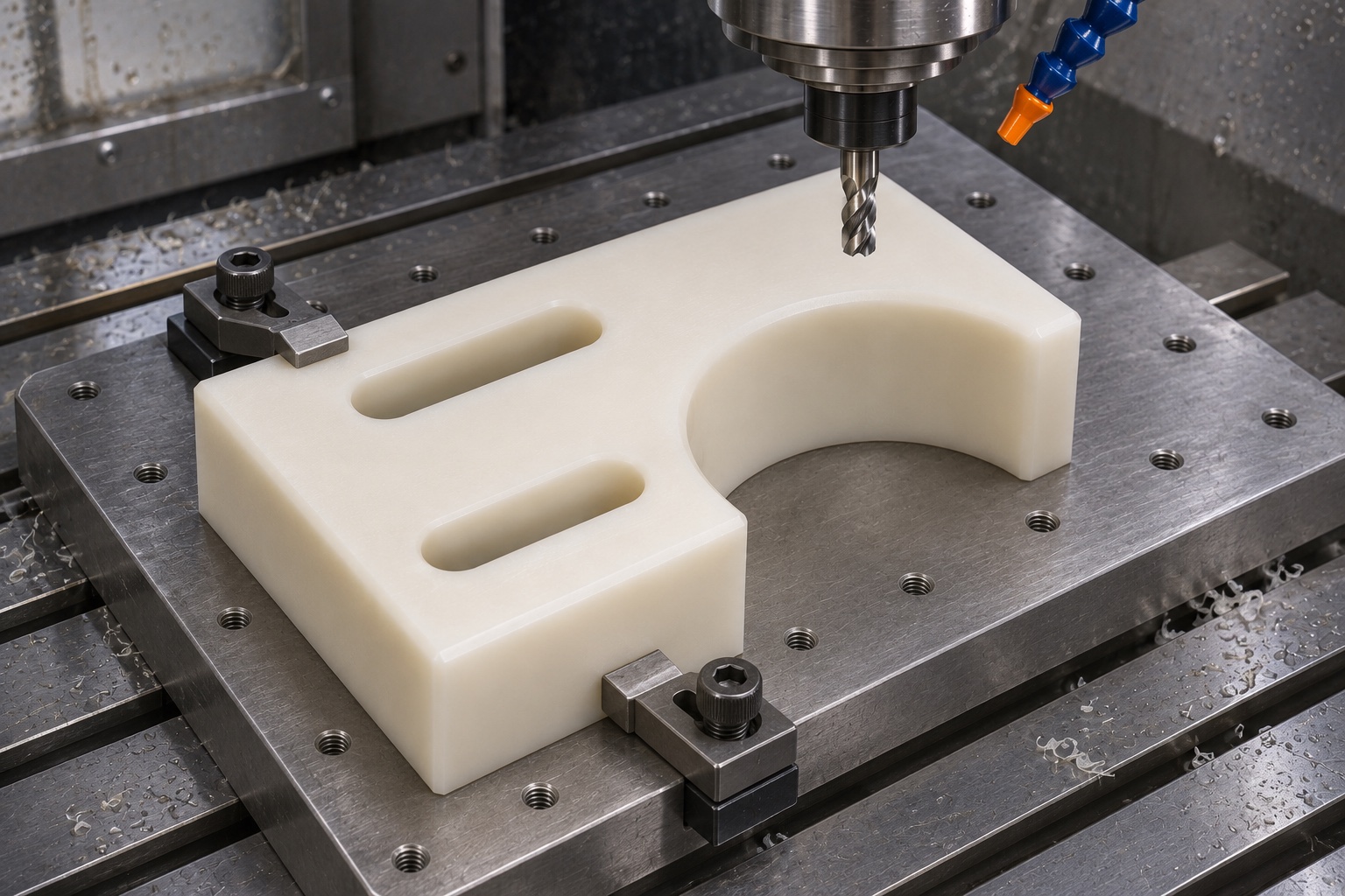
Rough the slots and open profile
Rough the open curve and the slots with stock left on the functional walls where needed. Review tool access at the slot ends, the underside and the concave transition. Keep the web supported as the two openings reduce its section. Release the part to assess movement under the specified conditions before committing to final geometry. If movement occurs, determine whether support, the stock or uneven material removal is responsible. Do not assume that an offset applied in the fixture will correct the released part. No deformation values or capability numbers are asserted for this example.
Finish with a controlled setup transfer
Relocate the released blank from the approved plane and reference feature. Finish the arc and slot walls without using the adjusting slots as an arbitrary origin. The program should leave the specified transition geometry at the entry and exit. Control tool engagement and chip evacuation so the contact wall is accessible for inspection. A finish pass that changes the usable wall height should be reviewed against the drawing, not accepted solely on a radius measurement. Remove raised material within the approved edge limits and then recheck the lower face and critical wall sections.
Diagnose a local catch on the inert reference
Suppose a plain container gauge touches near one end of the arc while the center radius agrees with the drawing. This is hypothetical, not a reported trial. Verify that the gauge is held at the correct height and that the support reproduces the selected adjustment. Inspect the transition, edge break and any local burr before reprogramming the entire curve. Check whether the gauge represents the intended container envelope rather than only a nominal cylinder. Document which contact occurs and where. If the boundary is ambiguous, ask the design owner to clarify the allowed geometry before changing it.
Diagnose reduced travel in the slots
Suppose each fastener fits through its slot but the mounted shoe cannot reach one end of the required adjustment. Check the slot orientation, relative position and available washer footprint on the approved plate. A slot with correct width can still have a misplaced end or an incorrect relationship to the other slot. Inspect the plate and hardware for mismatched revisions or burrs. Keep the problem separate from the arc fit; widening the curved wall does not restore adjustment. Any authorized revision to slot length or orientation should be evaluated for support and followed by inspection.
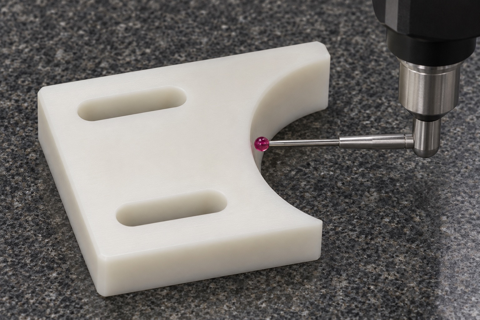
Plan a feature-based first-article report
List mounting-face form, slot dimensions, pattern position, arc profile and edge condition as distinct checks. Report the support, measurement height, alignment and condition after release. An accessible wall section may be suitable for a contact probe; if the required point cannot be reached, propose an approved alternative before accepting the inspection plan. Do not report only an average radius or a single fit result. If results are close to a limit, apply the agreed decision rule. The case provides no invented dimensions, lot results or pass rates. It defines the evidence that a real trial would need.
Use a bounded bench fit check
Use the approved mounting plate and inert reference to examine clearance at the agreed adjustment setting and contact height. Record orientation and observation without operating a labeler. Do not force the gauge through an obstruction or hand finish the part to make it fit. A successful bench observation applies only to the defined reference and conditions. It does not verify label alignment, adhesion, barcode recognition, throughput or wear life. If the actual equipment has different fasteners or the container range changes, the design owner must reassess the interface and any necessary system validation.
Protect the machined surfaces through delivery
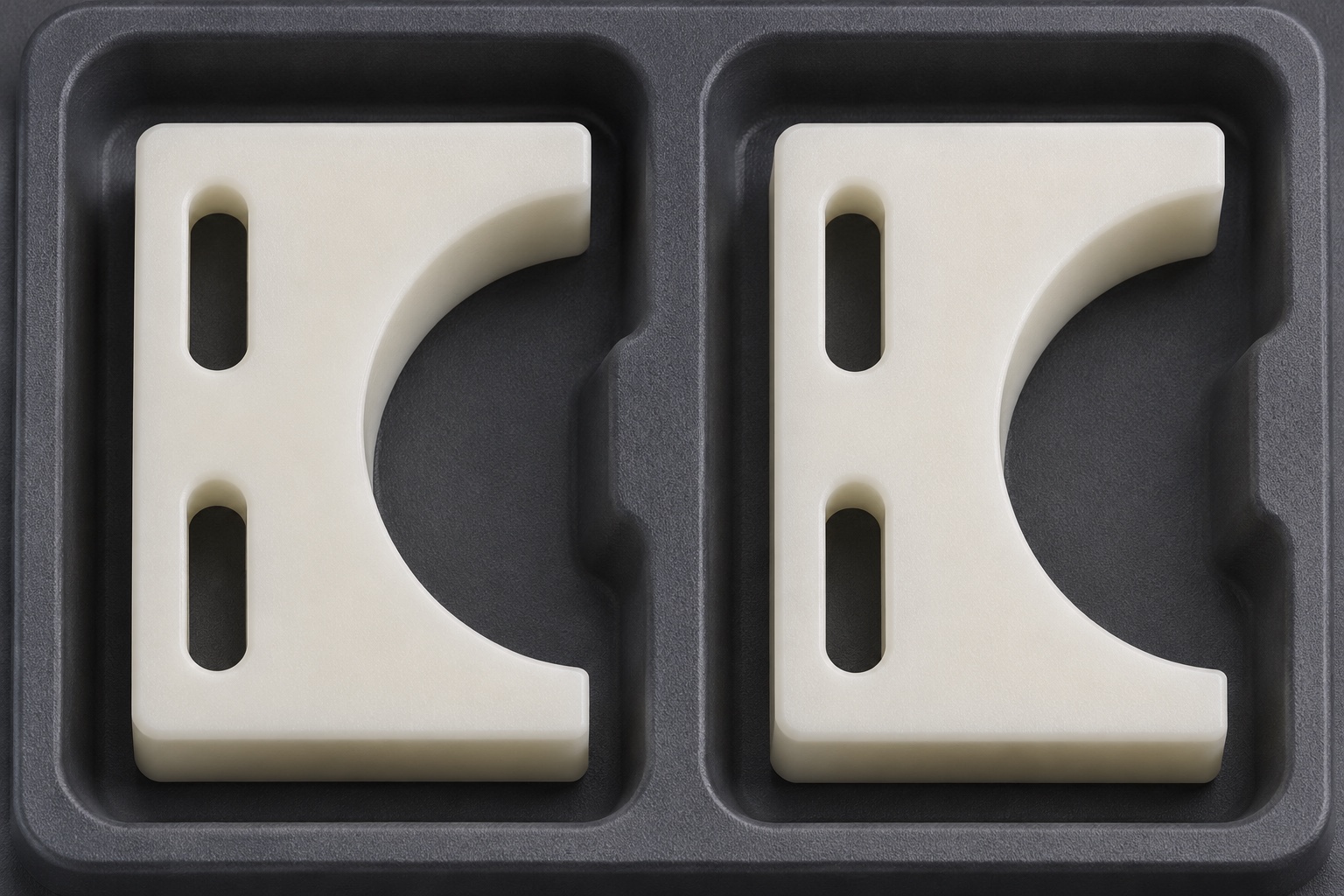
Remove loose chips and approved-process residues from the slots and concave wall. Inspect the edge condition and avoid scraping the wall during handling. Place the guide shoes in separate supported pockets so they cannot rub or bend at the tips. Keep labels and adhesives off the contact surfaces. The package may be evaluated for retention using inert parts, but it does not represent a validated sterile or clean packaging process. Record the actual packing condition and revision or lot identifiers required by the buyer. Any additional cleanliness or transport qualification is a separate requirement.
Handover separates geometry from system acceptance
The proposed deliverables include the controlled drawing, material identification, setup outline, feature measurements and packaging description. If requested, include the specific conditions and observations from the inert fit check. A first article that exposes uncertain travel or contact should trigger a drawing or fixture review before repeat production. This example offers a possible CNC route and review process, not a completed project or certified result. The responsible equipment owner retains decisions about container handling and labeling performance. Clear separation prevents a plausible machining report from being used as evidence for a process that was not tested.
FAQ
Is this a delivered customer part?
No. It is a representative CNC example. No customer order, inspection data or labeling performance is asserted.
Why rough before finish milling?
Roughing removes the main volume and allows review of shape after release. The final route should use the specified support and leave controlled finish allowance.
What if the gauge contacts only near the entry?
Verify gauge height, mounting adjustment and transition geometry first. Compare the local edge with the drawing before changing the main arc.
How can correct slot width still limit travel?
Slot length, direction and relative location also matter. Confirm the hardware and support footprint over the approved adjustment range.
Can the inert check demonstrate barcode quality?
No. It only addresses mechanical fit in the defined setup. Barcode and labeling performance require separate equipment validation.
What should accompany a real first article?
Include revision, material identity, measurements by feature, inspection conditions and agreed packaging. Add dry fit observations only if performed against the approved reference.

tanghangyun@oemach.com