
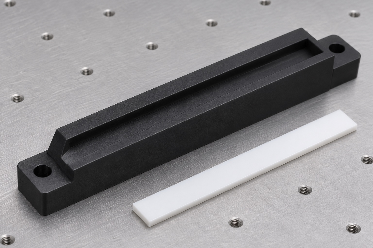
Set the example's boundaries
This representative machining example describes a black POM-C guide for the transport area of an imagined urinalysis analyzer. No actual customer order, device manufacturer or measured result is represented. The component is a narrow block with a straight shallow channel, an entry transition and mounting ears. The task is to review a possible CNC route that preserves channel shape after release from workholding. A separate fixture and an inert coupon are proposed for mechanical observations only. No live instrument, diagnostic specimen, reagent, test sequence or performance result is part of the example. The starting point is a controlled drawing, not a reverse-engineered part.

Ask how the guide is located
The example assumes that lower pads support the block and that a designated side feature establishes lateral location. The two end holes are treated as mounting clearance holes unless the designer specifies otherwise. Confirm the side reference, pad locations and approved wall contact before creating the inspection setup. A program that uses the midpoint of the holes as its origin may deliver a channel in a different position than a program referencing the side feature. The request for quotation should include a mating view, not simply tighter hole tolerances. If the locating scheme is unclear, resolve it before cutting a test blank.
Establish the incoming material record
Select only the drawing-approved POM-C grade and stock form. Match the lot record to the cut blanks, keeping labels off surfaces that will form the channel or mounting pads. The example does not select a grade on the basis of color alone. Review the stock geometry and the direction in which a blank is cut if relevant to stress and allowance. A material substitution would require approval even if it could be machined to the same size. Incoming material identification is also separate from reagent or device compatibility. The supplier's record shows which material was used, not where the device can be operated.
First setup: create reliable support
Prepare broad support faces on a blank with enough allowance for later finishing. Locate it against the defined stops, checking that the support beneath the part remains clear of loose chips. The proposed fixture supports the blank at several accessible regions without forcing an initially bowed part flat. Use only the restraint needed to resist the selected cut. The underside and side location will help the next setup relate the channel to the part's mounting references. Record the points used to locate and clamp so the same operation can be reproduced. An unexplained change in support would trigger a review of first-piece evidence.
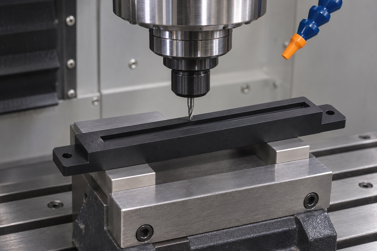
Rough the channel and release the blank
Rough the central channel, leaving a defined allowance on the wall and floor. Avoid leaving an unsupported thin wall for a heavy finishing cut. Release the blank and observe its shape on the agreed support under the specified inspection condition. The purpose is to see whether removal of material and clamping have changed the reference surfaces. If significant distortion is found, review stock, tool engagement and support instead of forcing the blank back to nominal. This example provides no measured deflection or allowable value. The drawing and the chosen measuring strategy determine which observations are relevant for approval.
Finish the channel and entry transition
Relocate the blank using the approved support and lateral reference. Finish the floor and sidewalls with a route that leaves access to the lead-in and avoids removing the locating length. Add the lead-in only to its defined extent. Check that the entry is smooth at the specified contact region, but do not judge the whole guide by how polished it appears. Finish the mounting holes and check the exit edges. The example reserves a separate step for edge cleanup because a cutter change or manual pass can affect the rim. Record the operation that creates each functional feature to support later troubleshooting.
Diagnose an entry that catches
Suppose the inert coupon catches at the entry although the central channel reading is within its limit. This is a hypothetical diagnostic scenario. First inspect the lead-in transition for a raised edge and confirm that the coupon corners match the reference definition. Then compare wall and floor readings at the entry height used by the coupon. A valid center reading cannot rule out a smaller section near the start. If the result changes when the part is reseated, check support and part bow. Do not enlarge the entire channel to hide an entry-specific condition; resolve the cause with the drawing owner.
Diagnose a width change after mounting
Suppose the free-state readings agree with the drawing but the mounted fixture shows a narrow region. Verify that the fixture applies the approved support and fastening condition and that the lower pads are clean. Compare readings before and after installation while keeping the measurement height fixed. Check whether the probe or the fixture itself can deflect a wall. If clamping is the cause, changing an offset in the milling program may produce a guide that is too loose when installed correctly. Document the result as an assembly-condition issue until the fixture and mounting requirements are confirmed. The example does not assign the fault in advance.
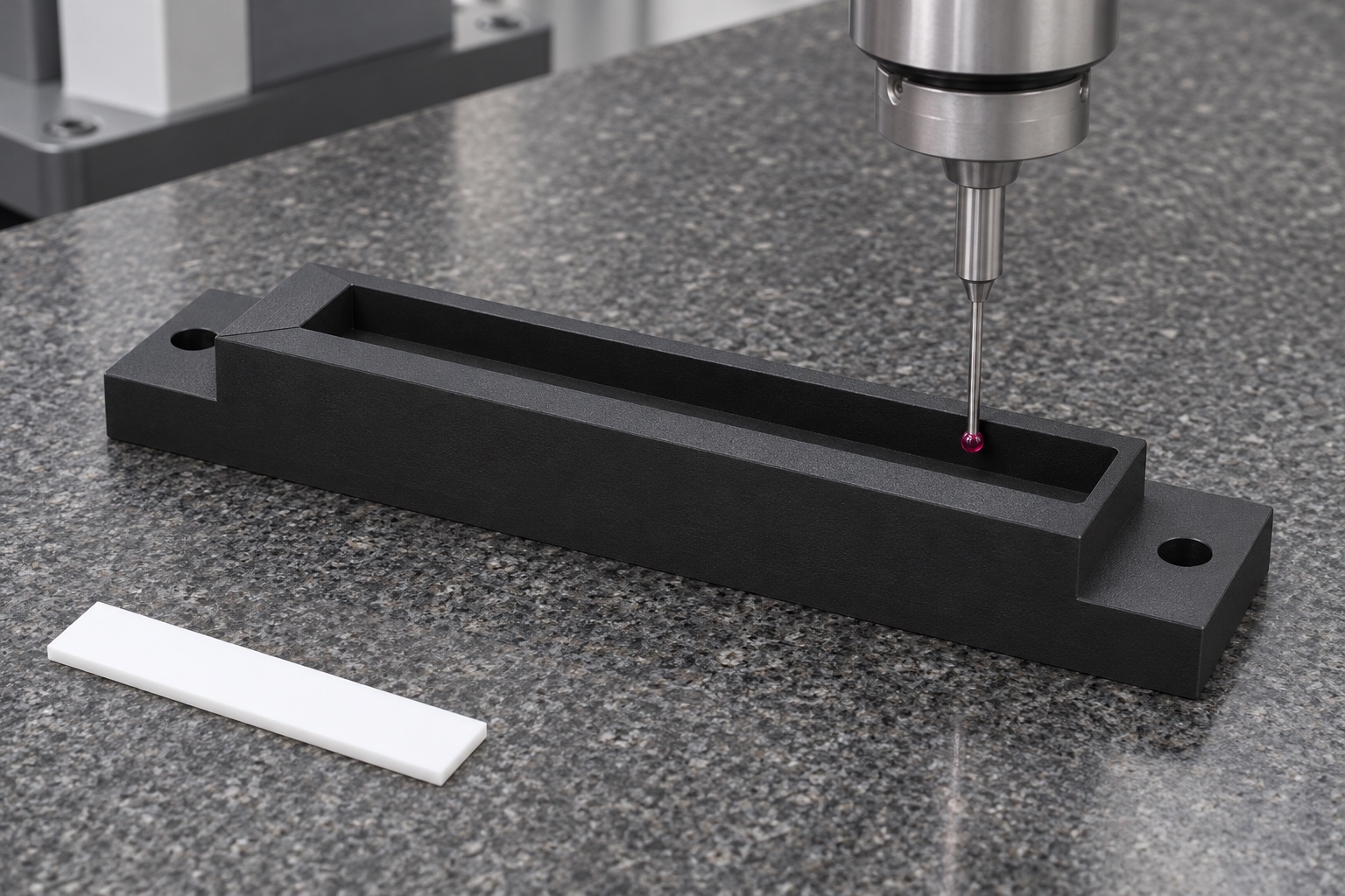
Specify a feature-by-feature report
The proposed inspection report covers lower pad geometry, mounting locations, channel width at the named sections, floor height and lead-in shape. Record which checks are performed free and which use a defined fixture. Choose a probe or optical method that reaches the required wall height and accounts for surface accessibility. Report the condition of the coupon separately from numerical results. A gauge check can complement the report when the contact is visible, but it should not obscure the traceability of the measured features. Results near an acceptance boundary should follow the agreed decision rule and not be rounded into compliance.
Clean without changing the channel
Remove machining chips and approved-process residues without scraping the functional walls. Inspect the narrow recesses and the exits of mounting holes. If a manual tool is used to remove a burr, confirm that it has not widened the entry or rounded a datum edge. A change in cleaning agent or process requires the applicable review for material and delivery requirements. This example assumes only an agreed component cleaning step and does not claim a validated reagent-contact or sterile condition. The supplier should describe the actual scope of cleaning and handling instead of applying a broad medical cleanliness label.
Check how the package carries the part
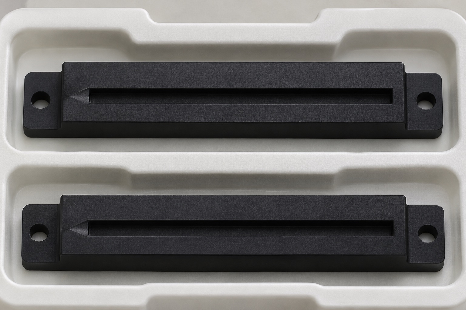
Use an individual pocket or separator that supports the guide outside the thin walls. A cover should retain parts without loading the entry rim. A bench packing trial can look for movement or rubbing using representative inert parts and the approved packaging material. That check does not establish transportation qualification or sterility. Tie the package identification to revision and lot where required, and keep adhesives and labels clear of the channel. If a change in packaging orientation places load on a functional edge, review the support before release. The proposed package protects the as-inspected geometry rather than correcting a part that has already bowed.
Define the first-article handover
The proposed deliverables are the approved drawing and material record, operation outline, dimensional results and notes from a dry fit observation if requested. Include the specified storage and packing conditions. Make clear that a geometry check does not validate analyzer performance. If the sample exposes ambiguity in the strip envelope or mounting constraints, stop to resolve that issue before repeating the route. No fabricated inspection results, tolerance capability statistics, certifications or customer acceptance appear in this example. The case illustrates how a buyer can review a process plan and decide what evidence to request before a custom part moves beyond first-article evaluation.
FAQ
Is this guide an OEM replacement?
No. It is a representative machining example and carries no claim of compatibility with a named analyzer, customer order or validated operating process.
Why release the rough blank?
Release allows observation of shape changes that may be hidden while clamped. It provides an opportunity to review stock and support before finishing the channel.
What should be checked when a coupon catches?
Check its geometry and the guide's entry transition, local wall width and floor at the contact location. Confirm that the support and orientation match the defined bench setup.
Can a dry check replace dimensional inspection?
No. It identifies some mechanical interference in a particular setup. Report the drawing features separately and do not use the check to infer clinical or transport performance.
Should a mounted check use extra pressure?
No. Use only the defined supports and restraint. Extra pressure can mask bow or narrow a wall spacing, making the result difficult to reproduce.
What evidence should accompany a first article?
Provide the controlled drawing, material identity, feature-specific results, inspection conditions and agreed packaging description, plus documented inert fit observations when requested.

tanghangyun@oemach.com