
The representative brief
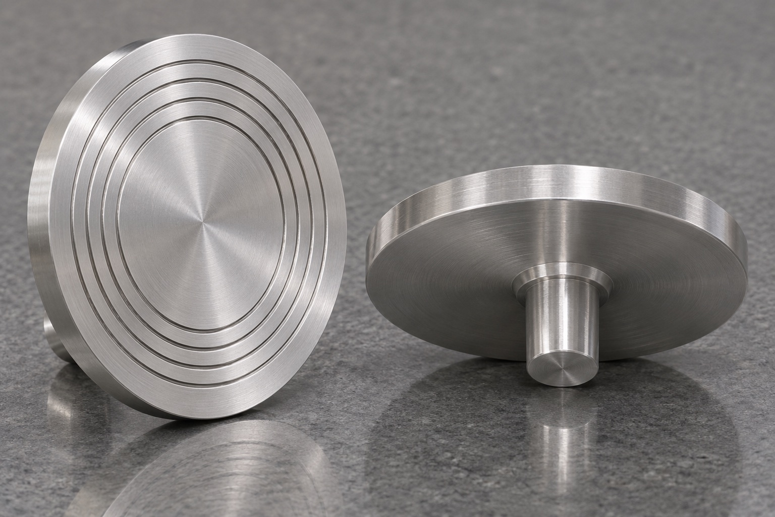
This is a representative machining example, not a record of a customer order or a validated device component. The part is a circular 316L disc with a grooved front face and a cylindrical rear stem. Its intended design references are the locating portion of the stem and a rear shoulder. The example asks how to quote and demonstrate geometric conformance when the front and rear features cannot all be reached in one setup. No instrument brand, model, clinical result or delivery quantity is assumed. The example ends with a proposed evidence package rather than a claim that this geometry was installed.

Review the mating section first
Before creating a toolpath, request a section through the mating holder. The section should show where the stem is supported, where the shoulder seats and what clearance is available near the transition radius. An outer diameter on the front disc does not determine these relationships. For this example, the design team would confirm that the rear shoulder, not the end of the stem, defines axial seating. If the actual assembly seats differently, the setup plan and checks must change. Marking those contacts in a review copy of the drawing is more useful than asking for an unspecified tight fit.
Establish stock and traceability
The example starts from round stock selected to leave sufficient material for the outer disc and the stem. The purchase description would identify the approved 316L form and any material record requested with the batch. Incoming checks should connect the stock identity to the job traveler before individual blanks are separated. The material label should survive the changes in physical form through a traceable lot record, not marks on functional surfaces. If stock dimensions or condition change, review workholding and finish allowance. Those changes may affect machining consistency even if the nominal material grade stays the same.
First operation: create the rear reference
In a proposed first turning operation, grip the rough disc allowance and expose the rear features. Turn the locating cylinder and finish the seating shoulder while they share the same spindle reference. Leave enough gripping stock and check that shoulder access does not drive the tool into the jaws. Use an approved relief if the mating corner needs it; do not add one simply because an insert is easier to program that way. Record the stem contact length and which surfaces the second fixture will touch. Before transfer, inspect the stem and remove loose chips without changing the seating land.
Second operation: locate on approved surfaces
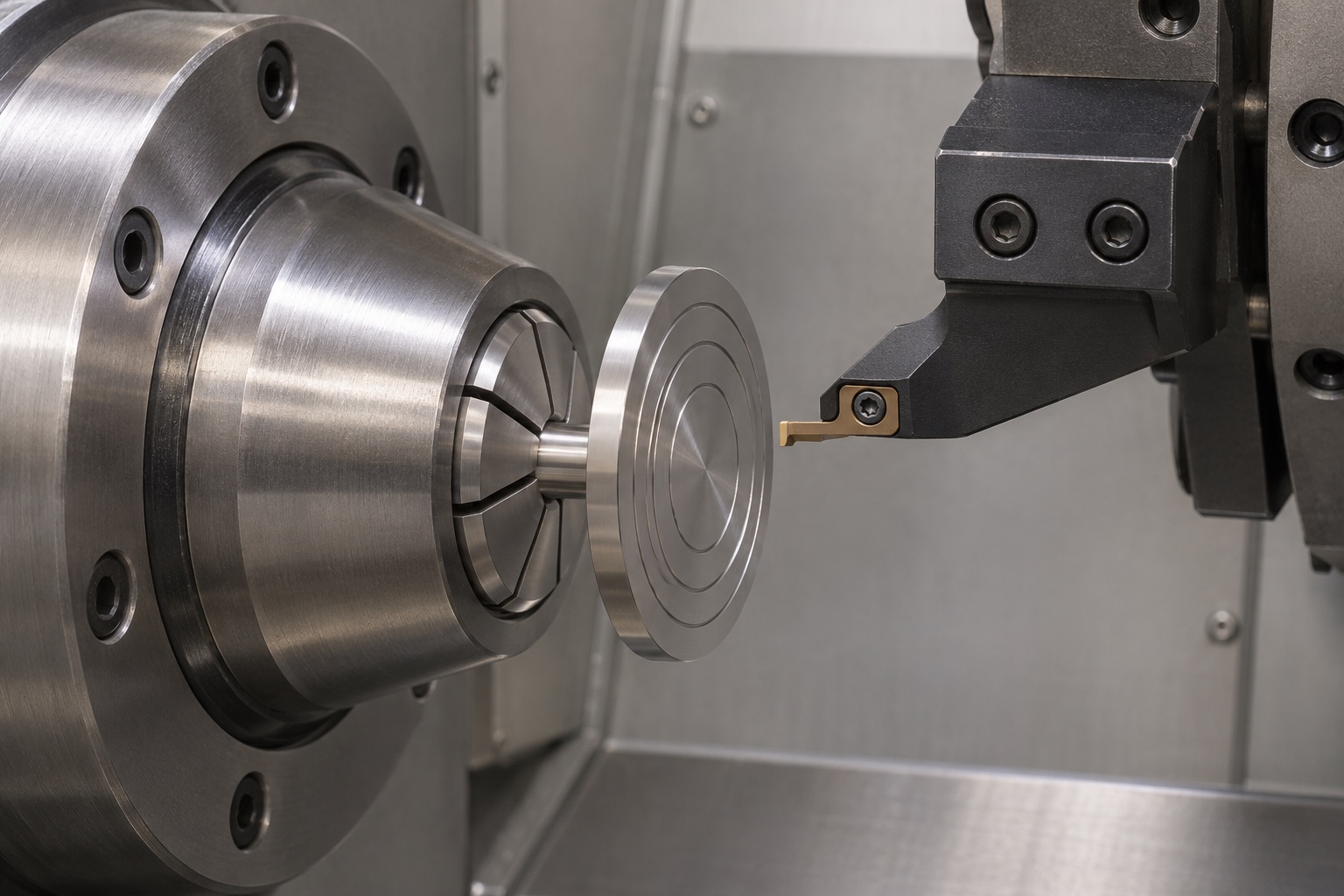
Use a bored fixture or collet that supports the intended locating portion of the stem. An axial stop references the agreed rear shoulder or other explicitly approved surface. The stop must not touch a fillet or debris. Confirm that the fixture resists cutting forces without marking the stem or flexing the disc. Set and inspect the fixture with a suitable reference before using it to interpret face readings. If repeat locations vary, investigate support and repeatability before changing dimensions in the program. Otherwise a tool offset may compensate for one seating event and worsen the next.
Machine the front lands and grooves
Finish the ungrooved face with a controlled allowance and cut the annular grooves using a tool compatible with the radius range and required cross section. Establish whether the drawing defines groove depth from the nominal face plane or from adjacent lands. Keep the operation order consistent so the finish cut does not alter depth after inspection. Check that chip removal and tool approach leave the rim and lands accessible. The proposed route treats the face grooves as features with their own inspection needs. It does not assign a tighter tolerance to the whole face just to compensate for unclear groove dimensions.
Consider a hypothetical seating problem
Suppose a sample stem enters an inert reference but the shoulder does not sit fully. This is a diagnostic scenario, not a reported result. Check the stem diameter over the relevant length, the shoulder transition, and contact marks at the bore edge. Inspect the reference itself for damage or particles. If contact is concentrated at the corner, compare the actual radii and reliefs before adjusting the diameter. A deeper insertion obtained by removing material from the stem is not evidence that the intended shoulder has been restored. Any modification to the defined interface needs drawing approval and reinspection.
Consider a hypothetical face variation
If axial indicator variation changes when the sample is rotated and reseated, isolate variation from the part and from the fixture. Inspect seating surfaces, repeat the seating sequence and evaluate a reference artifact where appropriate. Compare multiple tracks on the named lands, keeping the probe out of intentional grooves. If the variation follows the disc rather than the fixture, review the transfer setup and face finishing conditions. Keep form and datum-relative orientation separate in the report. An indicator result in one chucking condition alone cannot distinguish face form, stem alignment and a dirty stop.
Choose practical inspection access
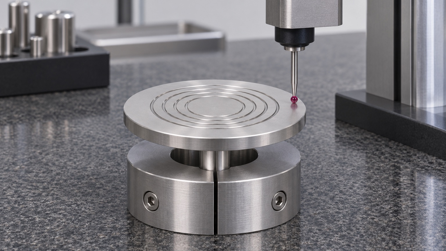
The inspection plan would list stem diameter, shoulder position, outer profile, face requirements and groove geometry separately. Use equipment that reaches the feature without spanning both flanks or misreading the land. A contact instrument may work on accessible lands, while an approved optical profile can help resolve a narrow groove. Report the locations and method rather than promising a particular precision number in advance. Use the agreed decision rule for readings near limits. Where first-article evidence is requested, retain the drawing revision, feature identifiers, equipment and raw results needed to review the decision.
Set an approved finish and cleaning sequence
Separate finishing operations from edge correction and cleaning. If a surface treatment is requested, agree how the stem and shoulder will be protected, and which dimensions will be checked after processing. For this example, groove debris and raised edges are explicit review points. Inspect them before packaging and use the requested cleaning procedure rather than inferring it from the word medical. Where no validated cleaning or sterile packaging process has been specified, make no such claim. The delivery documents can state what was actually done and which items were outside the agreed machining scope.
Plan a transport trial with inert parts
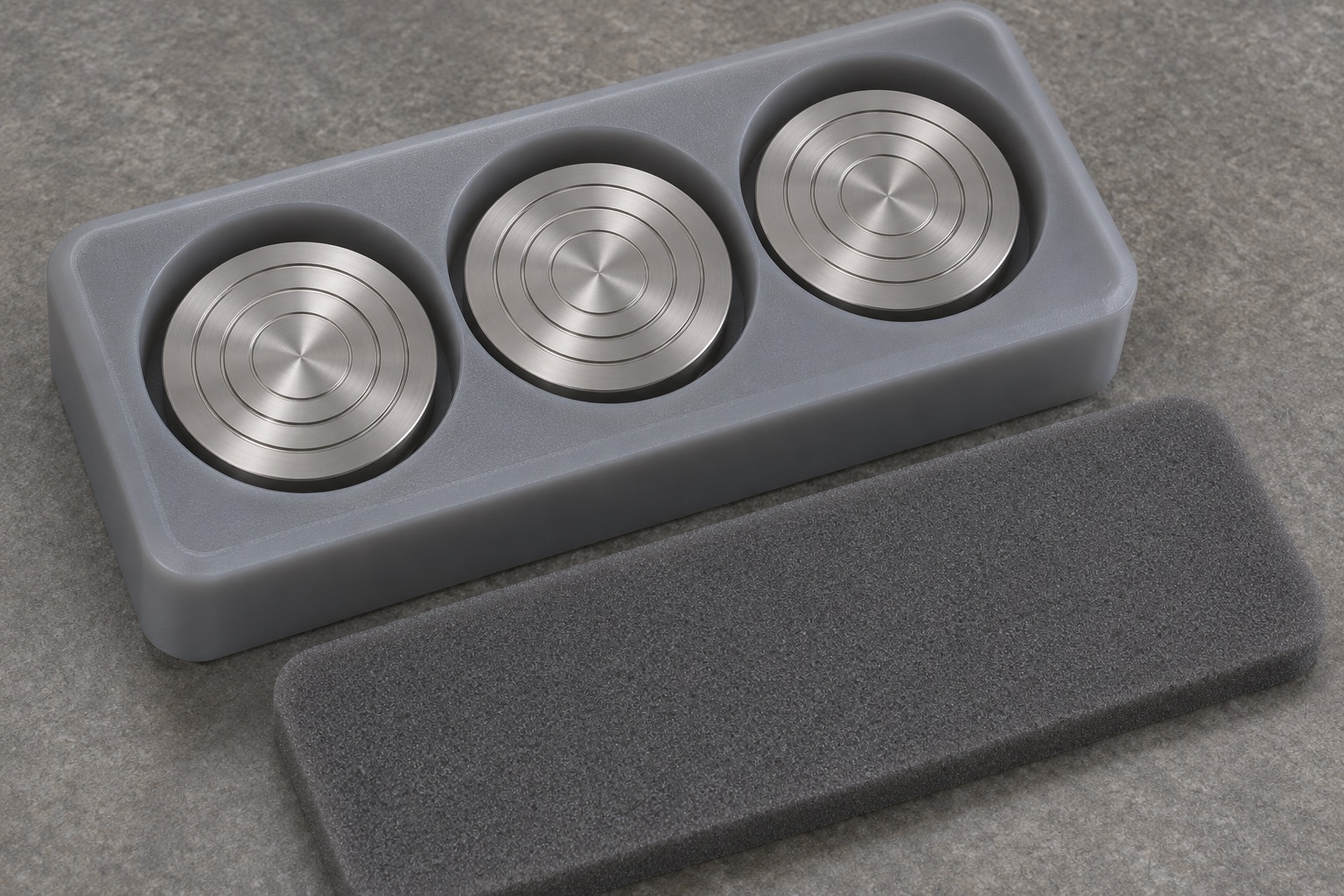
The proposed package keeps discs in individual recesses with clearance for rear stems and avoids rubbing the grooved face. Verify retention with an inert representative part and the approved packaging material, checking whether movement could transfer load onto a reference land. If parts can escape a pocket when the tray is handled, modify the packaging rather than adding tape to a functional surface. Use labels that identify revision and lot without marking the disc face. Where a buyer requests transportation qualification, agree a separate method and evidence package; this example does not claim that transit testing has been performed.
Define the handover and release gates
The proposed handover includes the approved drawing, material traceability, a setup outline, feature-specific inspection results and the packaging description. It distinguishes a mechanical gauge check from any required cold-condition or device evaluation. A buyer can use it to review process feasibility and decide whether to request sample parts. No fabricated measured values, certification or customer acceptance are supplied here. If the first article exposes ambiguity in the rear interface or groove definition, pause and resolve the drawing before repeat production. The objective is a repeatable machining decision, not a claim of performance in clinical use.
FAQ
Is this a completed customer order?
No. This is a representative manufacturing example. It describes a possible route and diagnostic scenarios, without a customer identity, lot size, measured result or claimed delivery.
Why machine the stem before the grooved face?
In the proposed two-operation route, the stem and shoulder provide reference features for the second fixture. The best sequence still depends on access, stock and the approved mating contacts.
What is the first check if the stem enters but the shoulder does not seat?
Review where the interference occurs. Compare the corner relief, shoulder and actual bore entry, and inspect both parts for debris before changing a dimension.
Why measure more than one face track?
Different radial tracks may show different axial variation. Sample the named lands and document the radius and setup. Do not mix groove depth with a face runout result.
Is clean protective packaging a sterile barrier?
No. Individual pockets can protect parts from contact and handling debris. Sterility requires a separately defined and validated process and is not asserted in this example.
Which documents are needed to quote a custom disc?
Provide the controlled drawing and model, mating section, material condition, groove and edge specifications, quantity, and agreed inspection and packaging scope.

tanghangyun@oemach.com