
Representative example and evidence boundary
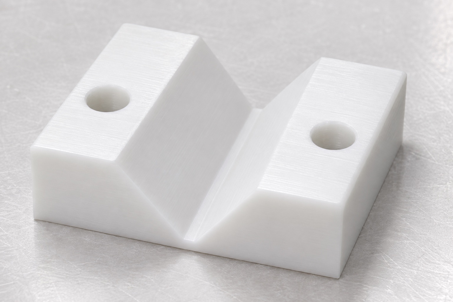
This representative medical plastic CNC machining case considers a POM-C frame support shoe for a lensmeter context. It is not a named customer delivery, an approved commercial replacement or an optical test report. No measured tolerance, frame-damage result or lens power accuracy is claimed. The geometry is a rectangular block with an open longitudinal V-groove and two mounting holes outside its contact region. The example explains the requirements a supplier would need before manufacturing and inspecting the part. Actual optical design, frame compatibility, device adjustment and qualification remain separate from acceptance of this individual support against a controlled mechanical definition.

Review the enquiry before selecting a cutter
A real project would start by reconciling model and drawing revisions and identifying missing contact information. A V-shaped groove in a rendering would not authorize the supplier to choose its angle, root condition or useful length. The quotation would state the material product, quantity, final condition and inspection scope. Approved mating geometry would be requested where it controls seating. This keeps price comparisons tied to the same interface rather than visually similar blocks with different contact behaviour. Any later change would be documented through the controlled revision, not introduced as an informal workshop adjustment after a single sample trial.
Define the intended faces and root clearance
The proposed review would identify the two useful inclined contact bands and distinguish them from entry edges and the groove root. Any permitted root radius or relief would be reviewed against the approved mating reference. A depth dimension would not be treated as a complete profile definition. The supplier would clarify whether contact at the root is permitted and what regions should remain clear. These decisions would be made before tool selection. The example does not invent a universal angle or edge condition; an actual order would need the device designer's approved interface and acceptance limits before a verifiable machining route can be released.
Establish mounting references without hidden assumptions
The base seating region and mounting holes would be related to the working groove through the specified datums. Individual hole diameters would be separated from pattern position and contact-face orientation. The supplier would confirm whether acceptance applies in the free state or a defined mounting condition. If mounting hardware influences that condition, its approved details would be included. Unspecified tightening would not be used to make the shoe conform to a convenient fixture. This ensures that the supplier's inspection evidence addresses the intended component rather than a shape produced by arbitrary support or a mount whose reference geometry was never approved.
Confirm acetal stock and its documentation
For an actual order, the approved POM-C grade, colour, stock form and documentation requirements would be confirmed before material release. Stock identity would remain associated with the part revision and manufacturing record. The case does not assume that every acetal product is interchangeable or that a white appearance establishes medical or optical qualification. Any conditioning, special cleaning or chemical-compatibility requirement would have its own approved scope and evidence. The supplier would identify the final acceptance state rather than compare measurements from undocumented material conditions. Proposed substitutions would require review before use, even when the nominal material name appears similar.
Plan supported material removal
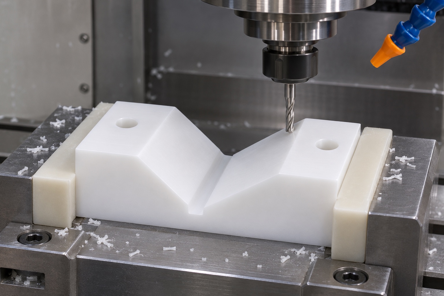
The representative route would review how to create the base, groove and mounting features while maintaining accessible references. The actual sequence would depend on dimensions, stock and equipment, not a universal recipe for plastic V blocks. No feeds, speeds or cycle times are claimed. The plan would identify useful faces that need protection during later work and features requiring reinspection after transfer. Generating several relationships in one setup could simplify reference recovery, but would not demonstrate conformity by itself. A real production plan would retain checks for the final component after operations capable of affecting the profile or the mounting interface.
Recover the reference during secondary work
If the block needed reversal or another fixture, the supplier would describe how the specified reference is recovered without loading the useful groove faces. Support beneath the base would be reviewed to avoid a favourable constrained shape that changes after release. Machining support would remain distinct from the final acceptance condition. If a mounted state were required, its approved details would be reproduced deliberately. Differences between observations would prompt a support and reference review before corrective cutting. The objective is repeatable evidence against the drawing, not one passing contact trial obtained by tightening, shifting or wedging the shoe until the reference appears to sit correctly.
Finish edges without erasing working contact
The finishing review would cover groove entries, root access, mounting holes and outside edges. Useful contact bands and groove length would be preserved. Any operation that could influence those features would trigger the appropriate reinspection. Loose material would be removed before a reference trial so chips are not mistaken for profile interference. Ordinary protective handling would not be described as validated medical cleaning or sterile delivery. This representative example also makes no claim that a support will avoid marking every frame material. Actual contact requirements and any relevant evaluation would remain explicit responsibilities of the controlled device project rather than assumptions attached to a polymer name.
Define inspection evidence by characteristic
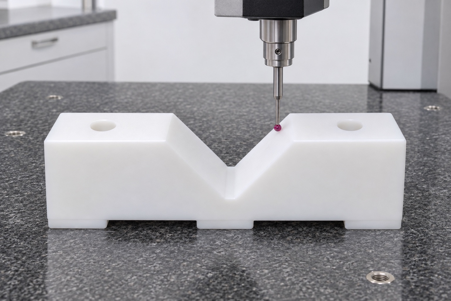
An example inspection matrix would separate profile angle and position, face orientation, useful length, root condition, base seating and mounting-pattern relationships. Each would have a defined reference, method and acceptance state. The selected instrument would need access to the actual working region, not just a convenient exposed section. Actual records on a real order would identify parts, revision, material condition and results against approved limits. This case contains no fabricated measurement table. If a feature could not be inspected as proposed, the limitation would be resolved before production rather than hidden behind a general claim that the component was checked on precision equipment.
Consider a hypothetical rocking observation
Suppose an identified inert frame reference rocked and appeared to contact one groove face before the other. This is a diagnostic scenario, not a reported manufacturing outcome. The supplier would preserve the observation and examine root clearance, entry edges, face definition, base support and reference alignment. Widening the complete groove would not be the automatic correction. A manufactured deviation would require an authorized disposition, while inconsistent design information would require clarification. After any approved work, affected characteristics would be checked again in the defined state. Reference identity would remain recorded so a different frame-shaped reference is not silently treated as equivalent evidence.
Keep contact evidence separate from optical testing
The inert comparison could show local contact and clearance without adjusting or operating a lensmeter. It could not establish optical alignment, lens measurement accuracy, compatibility across a spectacle range or clinical suitability. Those requirements would need separate evaluation by the responsible device organization. A component report would not approve a replacement for a named commercial instrument. Maintaining this boundary makes the representative case useful for procurement without turning a limited fit observation into an unsupported medical performance statement. An actual acceptance package would describe what was measured and observed, along with the specific limits of those methods and references.
Protect the contact geometry for transport
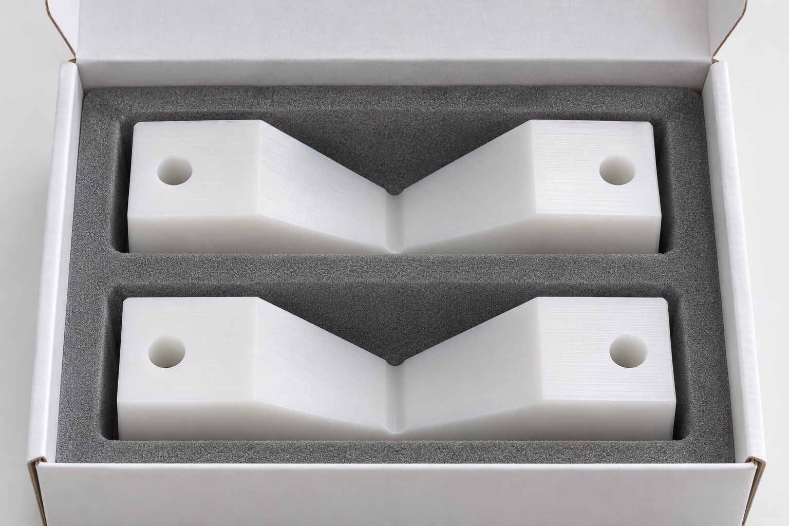
For shipment planning, individual separation would prevent working faces and groove edges from rubbing against adjacent components. Packing would support the base without wedging the groove or leaving fragments at its root. Part identity, revision and inspection records would remain associated with the shipment. A real enquiry would include approved files, material product, quantity, final state, groove and mounting definitions, relevant mating references, inspection scope and protective packaging. This representative route provides a concrete discussion framework without implying that a customer delivery, tolerance achievement, frame-compatibility test or qualification of a finished lensmeter has already been completed.
FAQ
Is this a documented customer manufacturing result?
No. It is a representative example with no claimed delivery, measured tolerance, optical accuracy result or completed compatibility evaluation.
Why define the root separately from the groove faces?
It may provide clearance rather than working support. The intended contact bands and permitted transition condition must come from the approved interface definition.
Can the supplier choose an angle from a rendering?
No. A visual V shape does not establish angle, useful length, position or acceptance limits. Controlled files and the relevant mating geometry are required.
What would be checked after a hypothetical rocking trial?
Review root clearance, entries, face definition, support and reference alignment. Obtain the required approval before correction and reinspect the affected features afterward.
Does a contact trial qualify optical performance?
No. It records limited mechanical contact, not optical alignment, lens measurement accuracy, broad frame compatibility or medical device qualification.
What must be approved for actual production?
Approve consistent files, material, quantity, final state, contact and root definitions, mounting references, inspection methods and protective packaging requirements.

tanghangyun@oemach.com