
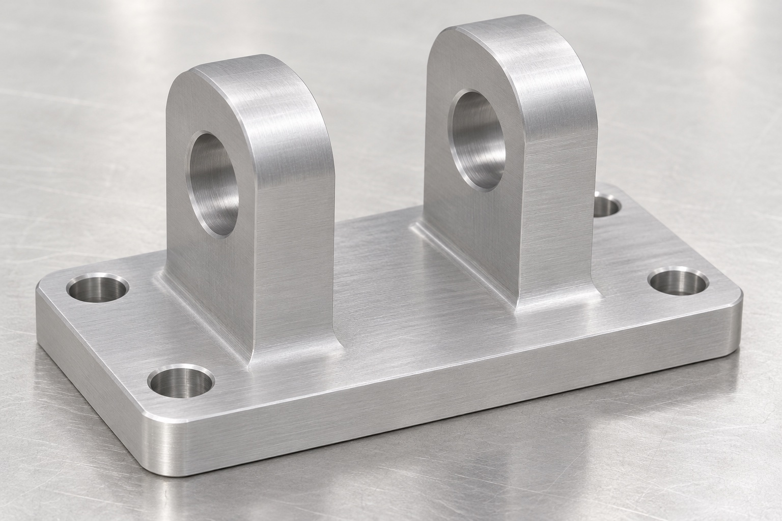
Representative mechanical manufacturing example
This representative CNC milling case considers a 6061 aluminum hinge block for the context of an electrosurgical footswitch. It is not a named customer delivery, a certified replacement or a tested electrical assembly. No dimensions, achieved tolerances, fatigue results or medical performance are claimed. The representative geometry consists of a base, two raised ears with pivot holes and a mounting pattern. The case explains how an actual supplier could plan manufacture and inspection from approved requirements. Electrical design, switching behaviour, pedal forces, ingress protection and device qualification remain outside this individual component's geometric acceptance.

Reconcile the drawing and model at enquiry
Before quoting a real part, the supplier would check revision consistency and request any missing definition of the pivot, ear spacing or mounting interface. A component photograph would not establish the intended clearance or allowable axis relationship. The quotation would state material condition, quantity, final finish and inspection scope rather than silently choose convenient workshop defaults. If a mating envelope controls interference, an approved reference would be requested. This keeps price comparisons tied to the same component. Later changes would follow controlled revisions so manufacturing, inspection and procurement do not proceed with different interpretations of an apparently simple hinge block.
Define the pivot and mounting references
The proposed inspection matrix would identify which base surfaces locate the block and how the pivot axis is related to them. Individual bore sizes would be separated from their mutual alignment and axis position. A pin-passage observation would not replace every specified geometric check. If a documented reference pin were required, its identity and permitted use would be recorded. The mounting pattern would be defined relative to the same functional references where appropriate. The supplier would resolve unclear datum recovery before production, particularly if a later machining setup uses a surface different from the one used for final acceptance.
Establish the ear spacing and contact bands
The useful inner ear faces would be distinguished from reliefs, corner conditions and edge breaks. A real drawing would define the relevant spacing and approved mating geometry. Overall width alone would not be used to infer the internal gap. The supplier would identify which surfaces may contact the mating reference and where clearance must remain. This example does not choose a pedal clearance or retention method. Those decisions belong to the controlled design. Any proposed access relief that changes a useful contact band would be reviewed before machining rather than added informally because a tool or gauge is difficult to position.
Receive and identify the specified material
The approved 6061 condition, stock form and required material documents would be confirmed for a real order. The representative case does not imply that alloy identity establishes electrical, corrosion or cleaning performance. Stock identity would remain associated with the part revision and manufacturing record. A proposed material substitution would require approval before use. Final treatment or marking requirements would have their own instructions and acceptance state. The supplier would distinguish actual documentation from assumed properties, and would not label an ordinary aluminum component as medically certified merely because its intended application is a medical equipment footswitch.
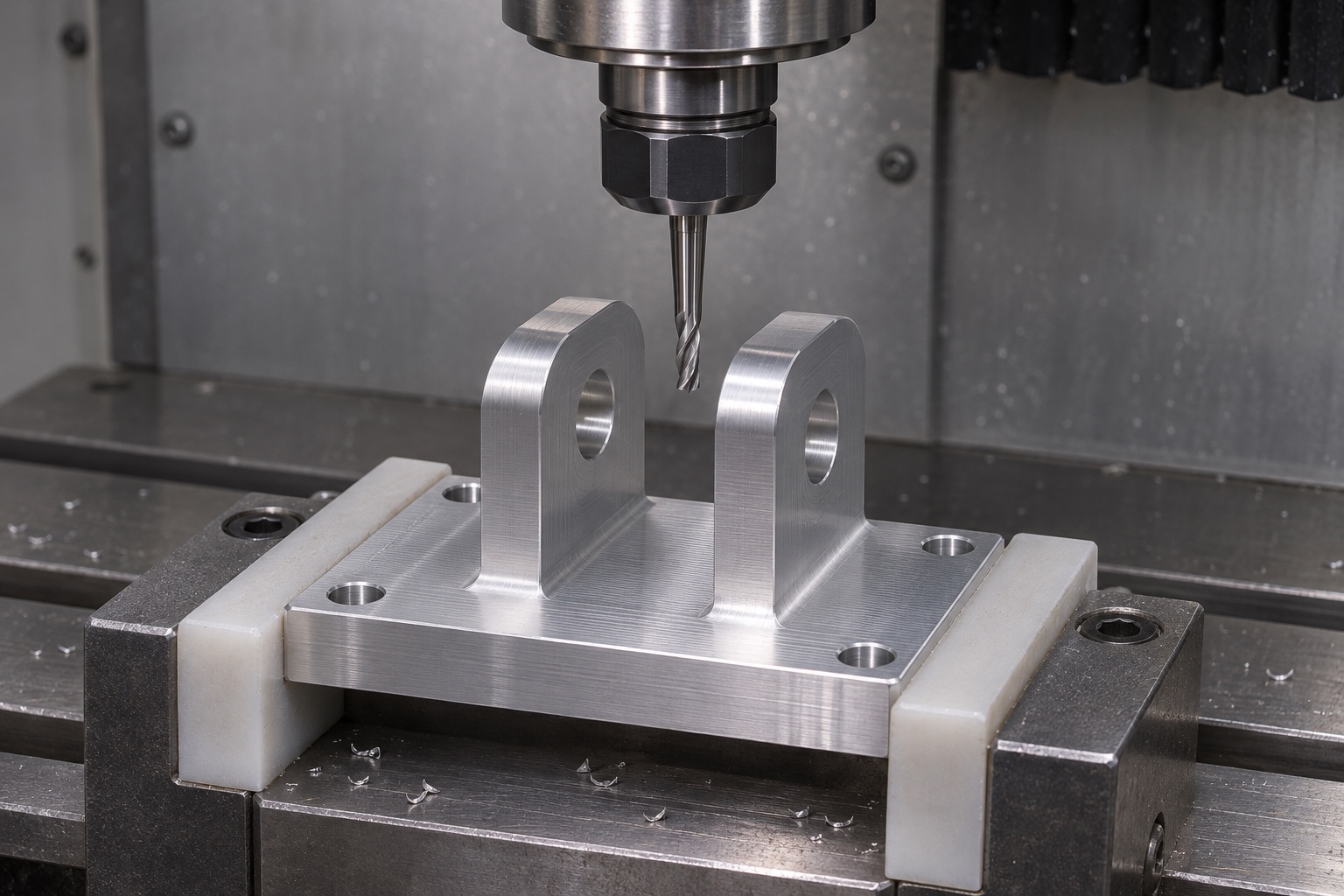
Plan the base and ear machining route
The example process review would consider access to the base, ear faces, bores and mounting holes while maintaining support. The actual route would depend on the drawing, blank and equipment, not a fixed recipe attached to the product name. No cycle time, feeds or speeds are invented. The supplier would identify useful reference surfaces and protect them during remaining work. A route with fewer setups could simplify transfer but would not prove conformity. The plan would still require checks after operations that can affect the final pivot relationship, mounting position or the spacing between the ears.
Control pivot access and reference transfer
If the pivot holes require work from opposing directions or a secondary setup, the route would explain how the reference is recovered. Fixture location and nominal tool coordinates would not be accepted as the only evidence of final alignment. The support beneath the base and near raised features would be reviewed so cutting or clamping does not create a favourable constrained form that changes after release. Any process revision affecting the pivot or contact faces would be documented. The intended acceptance state would remain distinct from the machining fixture, with actual measurements taken using the method and references approved for the order.
Finish the relevant edges in the final state
The finishing review would cover pivot entries, mounting holes, ear edges and the base perimeter. Useful bore support lengths and side-contact bands would be preserved. Features affected by approved treatment or edge finishing would be checked again where required. A smooth external appearance would not demonstrate that every working contact is acceptable. Ordinary chip removal would be kept separate from special cleaning requirements. This case does not claim sterile delivery, validated disinfection or compatibility with an unspecified cleaning process. The final inspection definition would identify the accepted state rather than allow a measurement from before treatment to stand in for the finished component.
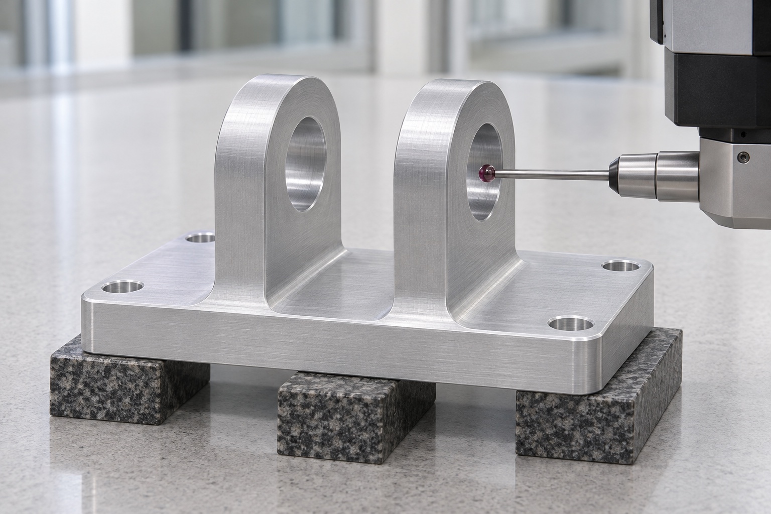
Build an inspection matrix without invented results
The representative matrix would list bore sizes, bore relationship, pivot-axis position, ear spacing, mounting-pattern location and useful seating surfaces. Each requirement would have a defined method, reference and acceptance state. Instrument identity and revision would accompany actual records for a real order. The method would be reviewed for access to useful surfaces, not selected simply because it can reach a convenient point. This example publishes no fabricated measurement table or tolerance achievement. An actual inspection report would need approved limits and recorded results for identified parts, with any unresolved requirement made explicit rather than hidden behind a general statement of precision.
Consider a hypothetical binding observation
Suppose an inert reference pin passes through one ear but meets resistance before entering the other. This is a diagnostic scenario, not a claimed production event. The supplier would preserve the observation and review bore relationships, entry edges, reference condition, support and drawing interpretation. Enlarging all bores would not be the automatic response. An identified manufacturing deviation would require authorized disposition; incomplete or conflicting requirements would require clarification. After any approved correction, affected characteristics would be inspected again in the specified state. Reference identity would remain recorded so a later passing trial is genuinely comparable to the earlier observation.
Retain the boundary to electrical device testing
A documented pin and inert mating reference could support a limited observation about passage, contact and clearance. They could not establish pedal actuation force, return behaviour, switching reliability, fatigue life, electrical safety or ingress protection. A material or finish name would not replace the separate evidence required for those functions. The responsible device organization would define system evaluation and any replacement authorization. The supplier's component report would remain focused on actual geometric acceptance. This boundary allows a useful medical machining example without implying that a complete electrosurgical device has been assembled, operated, tested or approved.
Protect the geometry and close the manufacturing scope
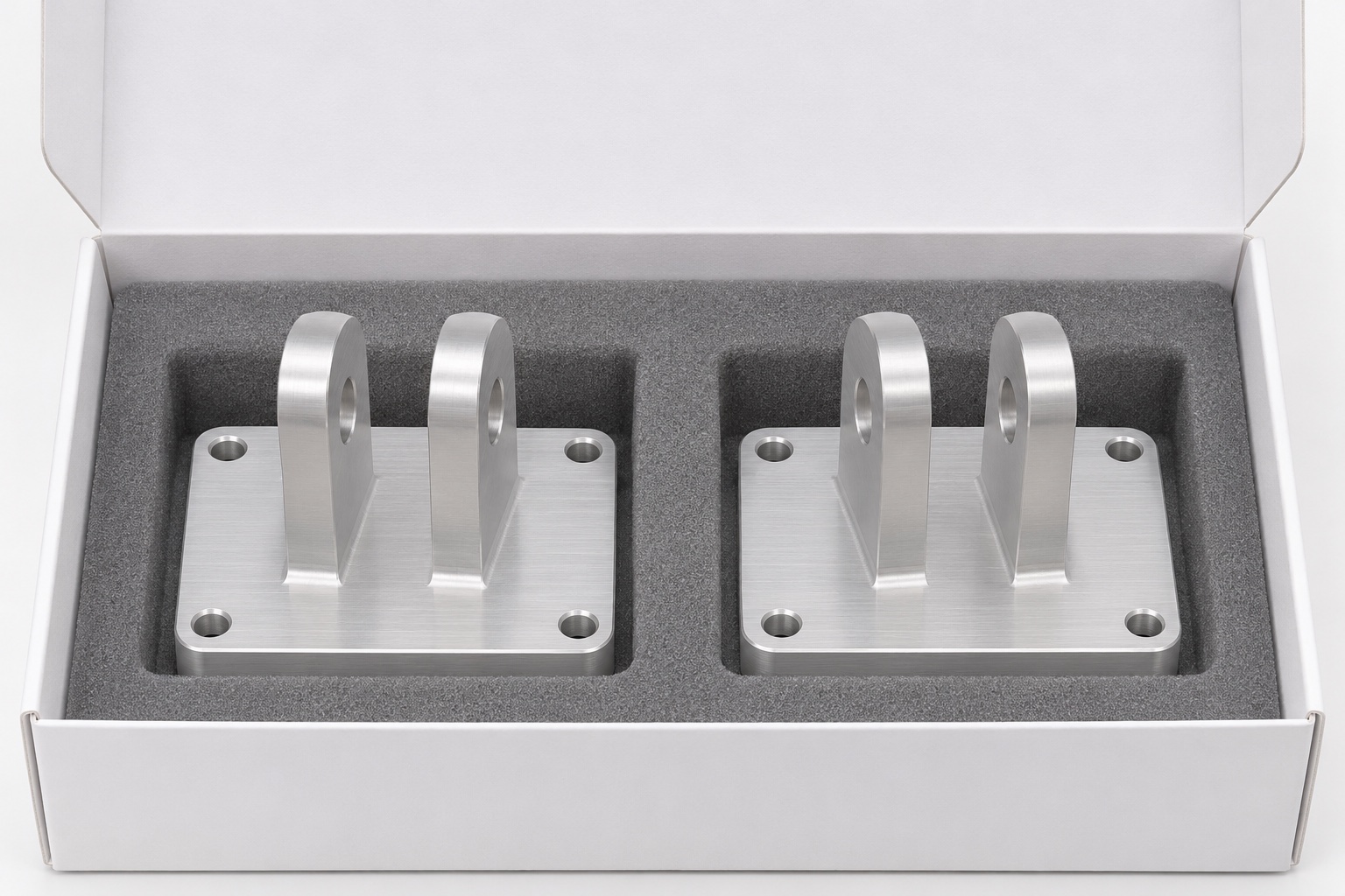
For transport, blocks would be separated so ear edges and pivot entrances cannot strike adjacent metal parts. Packing would support the base without pushing the ears together, and would avoid leaving fragments in working openings. Identification, revision and inspection records would remain associated with the shipment. A real enquiry would include approved files, material condition, quantity, final finish, pivot and mounting definitions, ear spacing, mating envelope, inspection scope and packaging. This representative route provides a concrete basis for procurement discussion without claiming an actual customer delivery, achieved performance or completed qualification of an electrical medical footswitch.
FAQ
Does this case describe a certified footswitch delivery?
No. It is a representative component manufacturing example. It does not claim a named delivery, certified replacement, measured result or completed device test.
Why measure pivot alignment separately from bore size?
Acceptable individual diameters do not establish the relationship between the holes or their position relative to mounting references. Those require separate defined checks.
Can the supplier choose the ear gap from a photograph?
No. Useful contact regions, clearances and mating geometry must come from the approved design, not be inferred from an application image.
What if an inert pin binds between the ears?
Record the observation and review alignment, edges, support and reference condition. Obtain the required authorization before corrective work, then reinspect affected features.
Does a finish establish electrical or ingress protection?
No. Those functions require separate requirements and evidence for the actual device. A machining finish or material label does not establish them.
What must be approved before production?
Approve consistent files and revision, material condition, quantity, final state, pivot and mounting definitions, ear spacing, inspection scope and protective packaging.

tanghangyun@oemach.com