
State the representative scope clearly
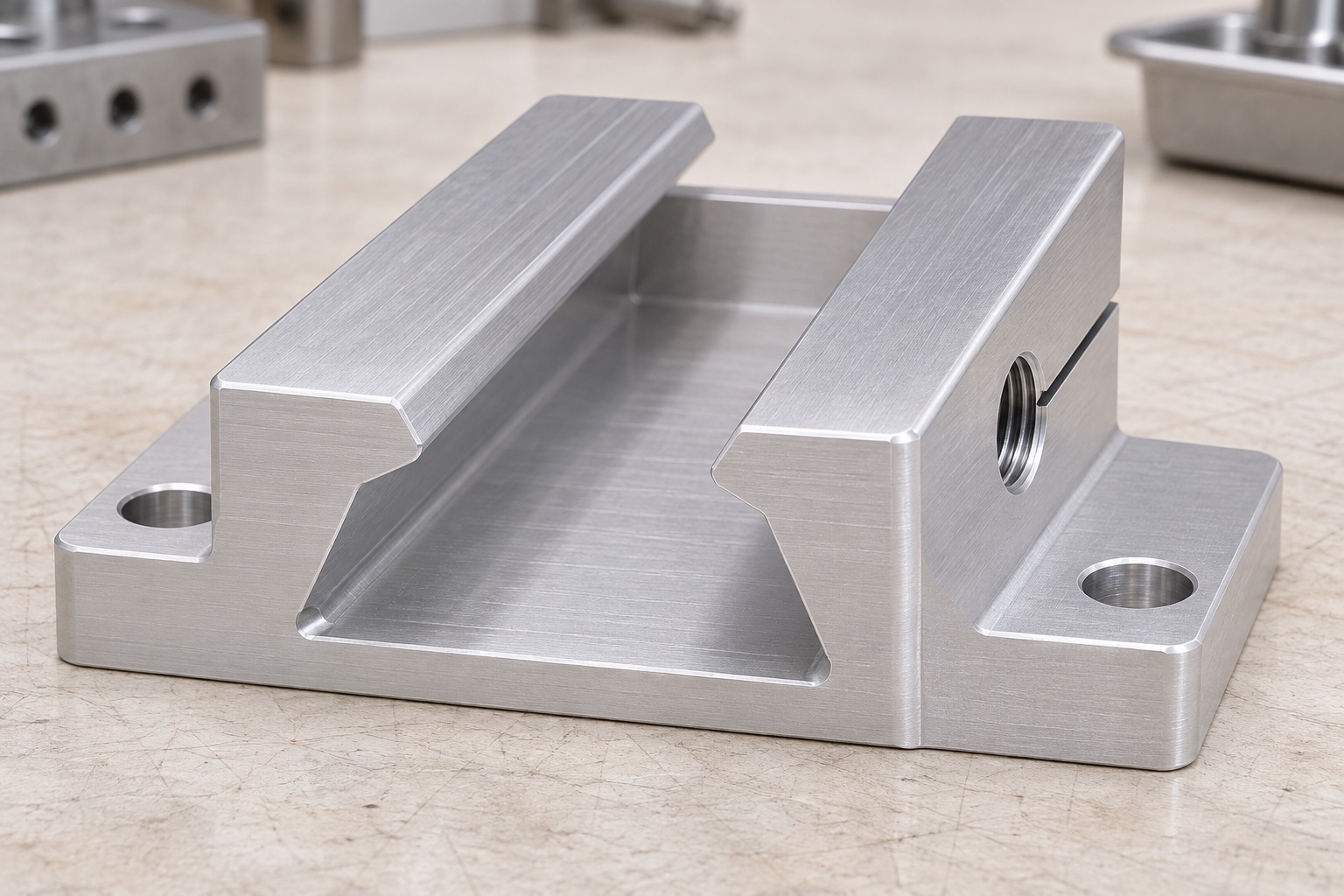
This representative CNC milling case considers a 6061 aluminum dovetail shoe in the context of a retinal camera support mount. It does not describe an identified customer delivery or present measured production results. No certification, holding-force value, image-quality result or device approval is asserted. The aim is to show how a machining inquiry can define contact geometry and inspect it against controlled requirements. The proposed component includes an angled rail interface, mounting references and a split region associated with a separately defined screw arrangement. A real project would require approved drawings and acceptance criteria, with complete mounting-system evaluation remaining outside this machining example.

Identify which surfaces actually locate
The representative geometry is a compact block with an open-ended dovetail interface and external mounting surfaces. The drawing must say which angled bands locate, which region is acted on by the clamp arrangement and whether the base contacts or provides clearance. Those roles cannot be determined reliably from appearance alone. Entry chamfers and corner reliefs are distinct from working engagement. The locating scheme also needs a relationship to mounting features. This prevents a supplier from treating an easy-to-measure exterior width as the entire specification. An accepted component must conform to a defined interface, not simply resemble a familiar rail clamp from another device.
Define the inputs to a real quotation
For an actual offer, the buyer would supply matching model and drawing revisions, 6061 material condition, quantity, final surface requirements and requested documents. The approved rail geometry would be included where it governs the contact profile. Screw identity, access and any specified assembly condition require definition as well. A photograph and a nominal angle do not establish full compatibility. Inspection and protective packaging expectations should be agreed before production. The scope distinguishes machining evidence from later tests of mount holding, vibration or camera alignment. That separation keeps quotations comparable and prevents an unspecified assembly evaluation from being assumed part of an ordinary dimensional inspection order.
Review the profile section and working length
The first proposed manufacturing review identifies the section used to define dovetail width and its relationship to angle and base reference. Measurements at different heights on an angled flank can legitimately differ, so the drawing needs an unambiguous convention. Useful engagement length is separated from chamfers and reliefs. The supplier evaluates whether the proposed tool can reach the required working bands and leave the specified end condition. Any requested relief or profile change must be approved by the designer. This example does not assert that a trial setup has already produced accepted parts; it describes how the relevant questions would be resolved before committing to manufacture.
Confirm aluminum and the final surface state
In a real order, incoming stock and documentation would be checked against the specified 6061 condition and traceability scope. A similar-looking alloy is not an automatic replacement. If an external finishing operation is required, the project identifies protected zones and final-state dimensions. The representative case does not choose a coating friction value, promise corrosion performance or infer functional behavior from color. Material and finish identity stay linked to the controlled revision. This is important when the flanks contact a rail: an observation made on an unfinished part is not necessarily evidence about the final assembly. The report must state the condition actually inspected rather than leaving it to inference.
Plan the tool approach and datum transfer
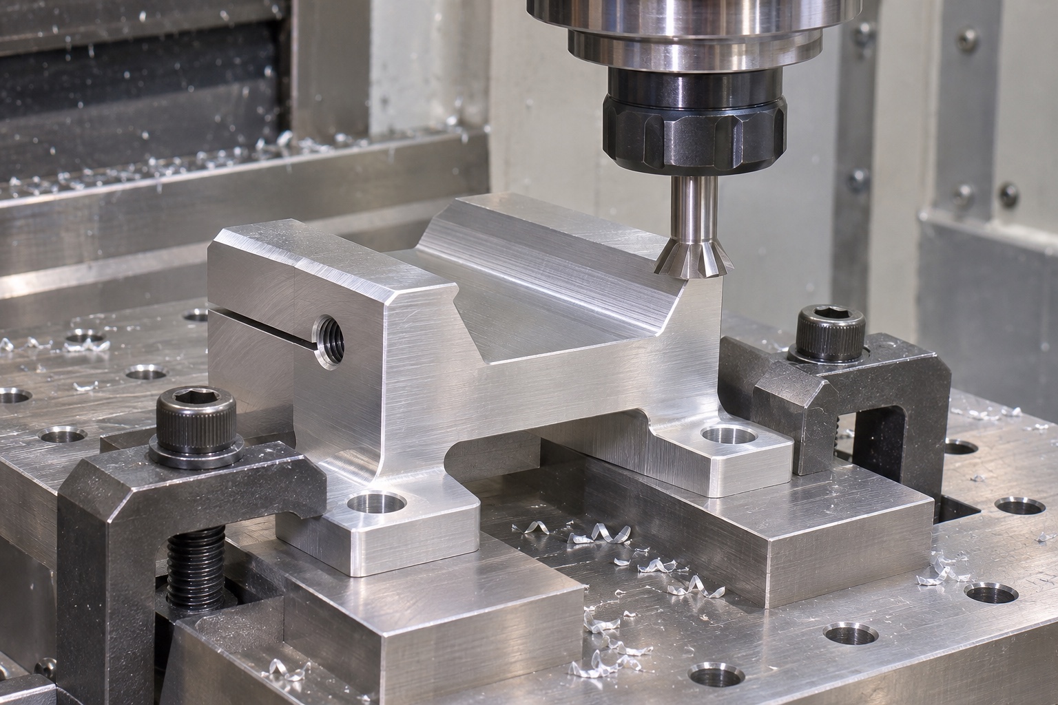
The proposed route considers the angled profile, mounting references and screw access together. Tool shape, approach path, reach and neighboring material must be evaluated for the actual geometry. A generic claim that all dovetails are simple to mill would not be sufficient. The supplier would explain which references are established first and how they are recovered after any setup change. No cutting parameters or production time are invented for this example. A useful process sheet preserves the relationship between the working flanks and the mounting features. It also identifies which later operations or finishes could affect that relationship and therefore require further checking.
Detail the split and screw interfaces
The split region needs width, termination and an explicit relationship to the screw feature. Thread identity and any clearance, head space or counterbore must match the approved design. The screw itself and the mating support belong to the assembly definition. Inspecting a thread does not determine holding force, safe load or permitted tightening conditions. The machining review instead addresses access, remaining section, local edges and dimensional acceptance. If a tightened-state measurement is required, it needs an approved procedure with identified components. The supplier should not improvise a torque or use available hardware merely to make the profile grip a reference rail during a bench demonstration.
Separate fixture restraint from accepted shape
The proposed workholding review identifies support regions that do not unnecessarily distort the split shoe. A vise can create a temporary shape unlike the free part or its specified mounted state. The plan therefore distinguishes machining restraint from the condition used for acceptance. If the requirement is free-state geometry, that condition must be measured. If it is a defined mounted condition, its details must be reproducible. This case contains no results under either condition. It highlights why an apparent profile mismatch should trigger review of support, load and surface state before blaming the material or altering the flanks to match a fixture-induced shape.
Finish contact entries and inspect affected areas
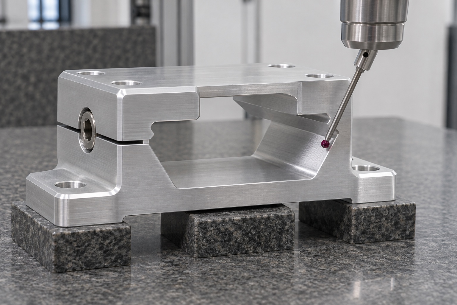
Raised material may remain at the entry, reliefs, split termination or screw features. An agreed finishing method removes it without erasing a working flank or changing useful length. Dimensions affected by that step need appropriate reinspection. A smooth exterior corner is not proof that internal regions contain no loose fragments. Where inspection access is limited, the method should be resolved before production. Ordinary removal of machining debris is not presented as sterile preparation or a medical cleaning validation. If the buyer needs a particular cleaning process or documentation, those requirements are defined separately with their own acceptance criteria and evidence, rather than inferred from a polished aluminum appearance.
Plan first-article evidence around the interface
A first-article plan would identify drawing revision, material and final finish, support condition and methods for inspecting the profile and mounting relationships. Angle, section width and useful engagement are distinct characteristics. Screw-feature position is not verified merely by passing a thread gauge. The method must reach the surfaces that define the interface without confusing relief with working contact. No tolerance capability or measured values are claimed in this representative case. A real report must be associated with identifiable parts and explain which characteristics were evaluated. Any limitation remains visible so a developer can combine the component evidence with separate mounting-system tests responsibly.
Investigate an inert rail mismatch without forcing it
If agreed, an identified inert rail could provide a limited dry geometric comparison. No patient, operating camera or powered instrument is needed. The setup would record rail definition, insertion direction, support and any specified condition of the split. As a hypothetical review situation, an early stop would prompt checks of entry geometry, relief, profile section, finish and reference identity. It would not justify forcing the rail or tightening an arbitrary screw until it moves differently. This is not a reported customer incident. A manufacturing deviation and a design conflict require different approved decisions; the initial contact observation should be preserved before either is corrected.
Protect the shoe and close the project scope
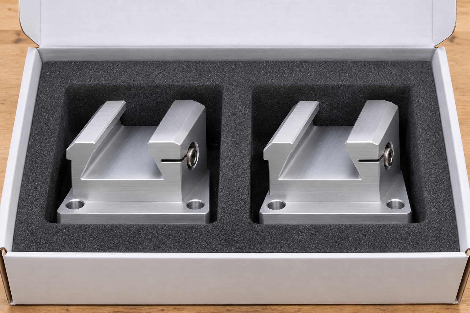
Packaging would keep shoes separated and protect working flanks, mounting surfaces and split edges. Support must not spread or compress the split region, and packing fragments should not enter the screw features. Revision and material records remain associated with the parts outside functional contact areas. Ordinary protective packaging is not called a sterile barrier. To proceed with an actual order, files, quantities, material, final finish, inspection scope and delivery protection must be approved. This case offers a concrete discussion of medical equipment component machining without inventing a customer, a successful delivery or a validated camera mount. Holding performance and clinical system suitability remain separate questions for the responsible organization.
FAQ
Is this a delivered and tested retinal camera mounting part?
No. It is a representative machining and inspection plan. No customer, completed shipment, holding-force measurement or device approval is asserted. Real projects require their own controlled requirements and evidence.
Why specify a section for dovetail width?
An angled profile has different widths at different heights. A defined section and method make measurements comparable and prevent two valid readings from being mistaken for a manufacturing discrepancy.
Does the example prescribe a surface coating?
No. Final finish and protected regions depend on the real order. The condition inspected must be documented, and coating behavior is not inferred from a part's appearance or a generic aluminum designation.
Can a split shoe be accepted while clamped in any vise?
No. Arbitrary restraint can change the observed profile. Acceptance follows the specified free or mounted state, with known support and assembly details rather than convenient temporary pressure.
Does an inert rail fit demonstrate secure camera holding?
No. It gives only the recorded geometric observation. Holding force, vibration response, camera alignment and clinical suitability require separate evaluation under approved conditions and cannot be derived from a fit trial.
What is needed before requesting manufacturing?
Provide matching files, material condition, quantity, final finish, contact and profile definitions, rail and screw information, acceptance state, inspection evidence and packaging requirements. Resolve open access and geometry issues before placing the order.

tanghangyun@oemach.com