
Describe a representative mechanical insert honestly
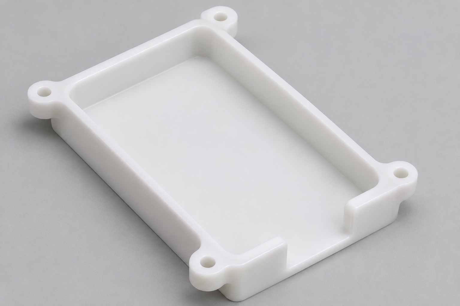
This representative precision CNC case considers a POM-C battery tray within the housing context of a portable ECG recorder. It is not a customer delivery report and contains no claimed certification, test data or device approval. The proposed part is a mechanical insert with a shallow pocket, defined support regions, mounting features and an end opening. It does not constitute a battery pack, charging system or insulation design. The purpose is to explain the information needed for a real manufacturing plan. Dimensions and acceptance criteria would have to come from approved project documents, while electrical and medical device evaluations remain separate responsibilities.

Assign functions to the pocket and mounting features
The representative geometry separates the pocket floor, surrounding walls, an end notch and external mounting regions. Those surfaces should not all be assumed to carry the same contact or restraint function. A drawing needs to identify intended seating pads, clearance areas and the references that locate the tray in the enclosure. The pocket may accommodate only a specified inert envelope during an initial mechanical review. The actual pack and any retainer require their own approved definition. This division gives the manufacturing supplier a clear basis for reviewing shape and inspection without guessing which surfaces the device designer intended to use.
Gather the inputs for an actual offer
A real inquiry would include a controlled model and drawing with matching revisions, the POM-C grade, stock or document requirements, quantity and final surface condition. It would identify the mechanical envelope that governs pocket fit and the housing geometry that governs mounting. A photograph of a battery or recorder is not enough to assign tolerances or corner clearances. Inspection scope and packaging requirements belong in the inquiry as well. The parties should distinguish a machined-component inspection from any later battery or device evaluation. That distinction prevents suppliers from quoting different assumptions while each believes it is manufacturing the same simple tray.
Review contact regions and corner access
The first proposed design review compares pocket contacts with the approved envelope and considers tool access to internal corners. A cylindrical cutter leaves radii, so the required shape must be compatible or include an approved relief. A supplier should not enlarge the whole cavity until a sample fits. That could change restraint, wall section or mounting space. The end condition and useful support depth need clear definitions. If a revision is required, drawing and model are updated together. This case describes the review approach only; it does not assert that a particular tool route or trial part has already been accepted by a device manufacturer.
Keep material identity separate from device approval
For an actual order, incoming stock would be confirmed against the requested POM-C grade and traceability scope. Another acetal grade is not an automatic replacement. Storage, conditioning and any subsequent process must be agreed where they affect acceptance. The color of a plastic block does not prove its identity or its suitability for a medical electrical application. This example contains no material certificate and does not claim that POM-C alone supplies an approved insulation barrier. It shows where evidence would be requested and associated with the manufactured tray. A real design must separately determine whether that material and geometry meet its intended-use requirements.
Plan cavity machining around the remaining section
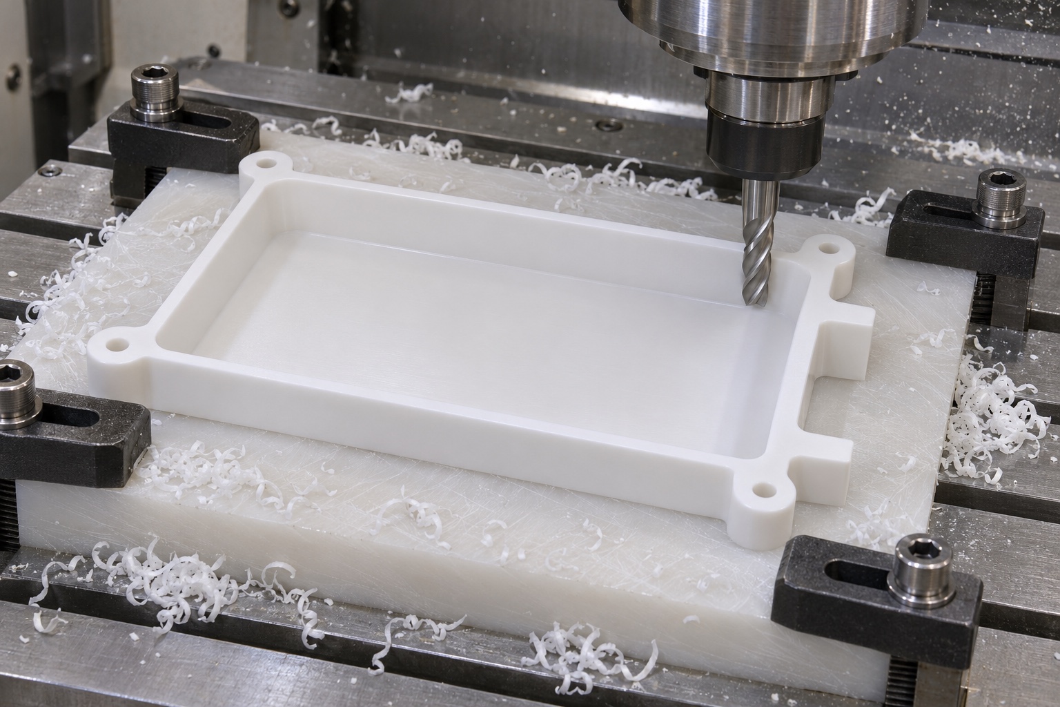
The proposed route evaluates the pocket, wall and floor sections before choosing support and machining order. Removing a broad cavity changes the blank's response to clamping. The supplier needs to consider that change rather than selecting a sequence solely from the outside dimensions. Reference surfaces should remain recoverable for later mounting-hole and end-opening operations. No universal cutting conditions, cycle time or production capability is claimed here. The actual grade, stock, geometry and equipment govern those decisions. If the part is transferred between setups, the plan explains where it is supported and how the next operation retains the approved relationship to the enclosure mounting face.
Position the end opening and mounting pattern
The end notch is a defined clearance feature, not an informal cut made wherever a cable appears to fit. Its location and usable envelope need a relationship to the pocket and housing. Mounting holes likewise require position relative to the functional seating references, not merely correct individual diameters. A rear connector volume may govern access even when the top view looks unobstructed. Those requirements must be supplied by the design owner. The manufacturing review should identify tool and inspection access, local remaining material and any proposed change needing approval. It must not invent electrical separation distances or cable requirements that are absent from the controlled design.
Distinguish workholding from acceptance support
The planning review considers broad appropriate support and contact forces that do not distort the thin floor or walls. A tray pressed flat against a fixture has not necessarily demonstrated its free-state form. Conversely, if acceptance is specified in a mounted state, that state must be reproduced rather than replaced with arbitrary clamping. The inspection method should record support locations and the relevant condition. This representative case offers no measurements under either state. Its lesson is that a meaningful comparison needs consistent support. A discrepancy between readings should first trigger a method review, not an automatic conclusion that the machine, material or operator is at fault.
Finish pocket entries and inspect affected contacts
Loose fragments at the pocket, mounting holes and end opening need removal using an approved method. Finishing must not erase a support pad or create an unapproved entry that changes contact. Areas affected by a geometry-changing finishing step are checked again. A smooth feel at the outer rim does not establish the internal corner or floor condition. The plan keeps ordinary chip removal distinct from any special cleanliness specification. It does not claim sterile delivery or electrically safe handling based on appearance. If the buyer needs particular residue limits or cleaning documents, those are agreed as separate defined requirements before the manufacturing order proceeds.
Plan evidence from identifiable features and parts
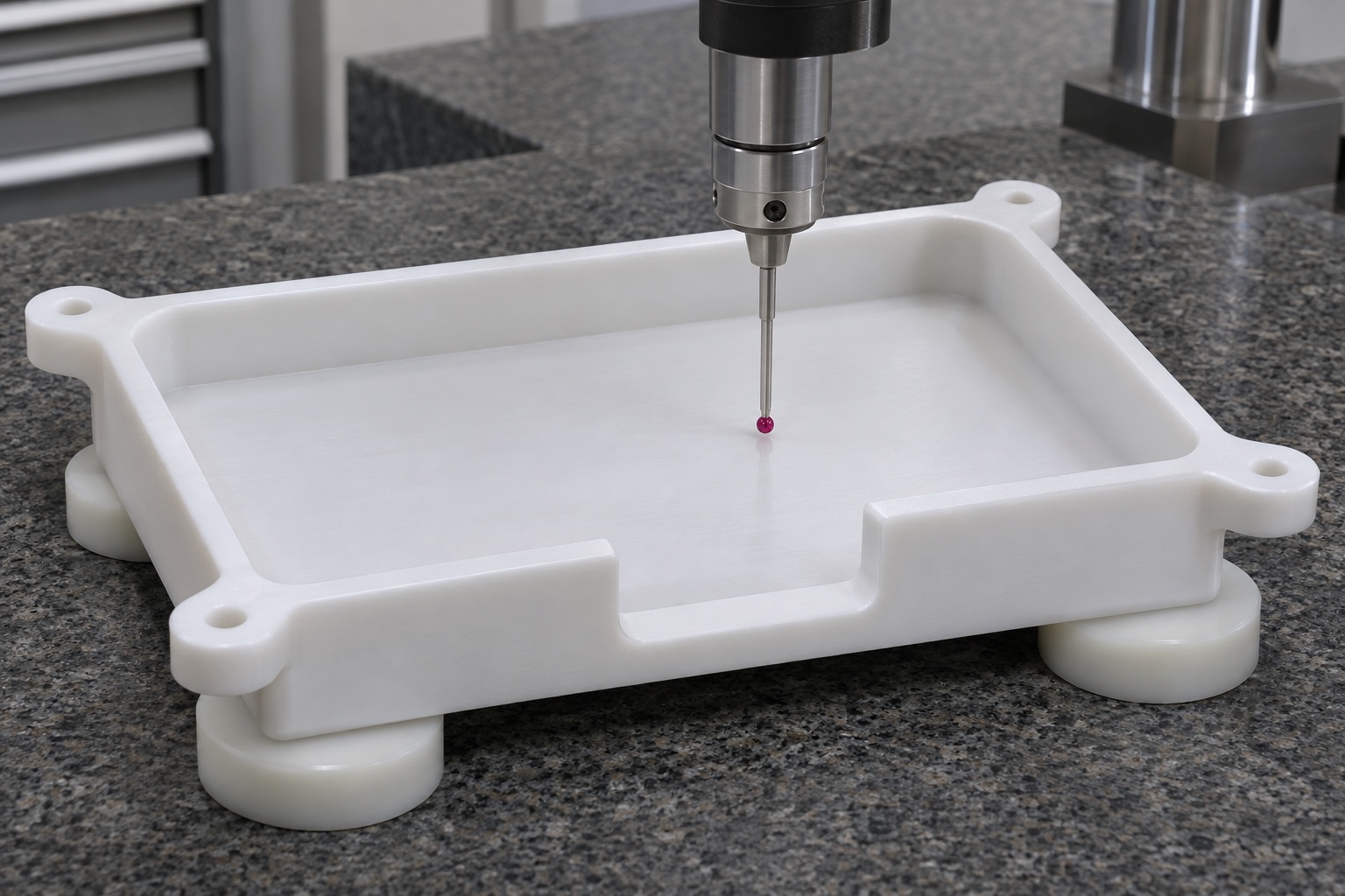
A first-article inspection plan would identify the revision, material condition and method for evaluating pocket support, usable depth, end clearance and mounting relationships. Instruments should reach the intended surfaces without introducing unnecessary deformation. A measurement of outer length is not evidence that the internal envelope or mounting pattern is correct. This case publishes no numeric results or acceptance rates. In a real project, records must be associated with identifiable parts and show what was actually checked. Features not covered by a particular method remain explicit. That makes the report useful for a device developer who must combine component evidence with other separate evaluations.
Investigate fit with a non-electrical inert envelope
If agreed, an identified inert reference could be placed in the tray under a documented orientation and support condition. No live cell, charging circuit or powered recorder is needed for that geometric observation. An early stop would prompt a review of corner radius, end clearance, raised material, insertion direction and reference identity. It would not justify forcing the reference or cutting the pocket larger immediately. This is a hypothetical investigation, not a reported customer problem. A manufacturing deviation and a design conflict require different dispositions. The recorded comparison cannot establish thermal behavior, restraint under service loads, insulation safety or compliance of the completed recorder.
Protect the tray and close the contractual scope
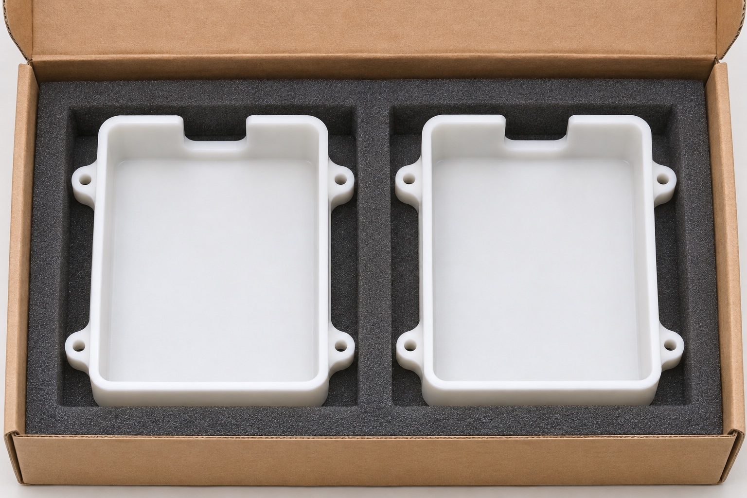
Protective packaging would separate trays and support appropriate regions without flexing the floor. Packaging fragments should not collect in the cavity or end opening. Identification remains outside specified contacts and accompanies the controlled revision and material record. Ordinary protective wrapping is not called a sterile barrier. To turn this case into a real project, the parties must approve files, quantity, material, final state, inspection scope and delivery protection. The example provides a concrete manufacturing discussion without inventing a customer, delivered batch or electrical result. Battery selection, charging design and qualification of the medical recorder are not transferred to a machining supplier by a successful dry fit.
FAQ
Is this a real delivered ECG recorder battery tray?
No. It is a representative mechanical manufacturing plan. No customer, completed delivery or device acceptance is asserted. A real project requires its own approved files, requirements and documented evidence.
Does the example choose a battery chemistry or charging system?
No. It describes the machined insert and a specified mechanical envelope only. Battery and electrical design require separate decisions and verification by the responsible device organization.
Why should the pocket floor and walls have assigned roles?
Some regions may support while others provide clearance. Assuming every wall is a restraint can introduce unintended contact. The drawing should identify those functions and relate them to the approved envelope.
Can machining and inspection use any convenient clamp pressure?
No. Workholding and acceptance conditions must be considered separately. A forced shape may conceal a difference in the free part; any required mounted condition needs a defined reproducible setup.
What does an inert envelope comparison establish?
Only the observed mechanical fit under the recorded conditions. It does not prove thermal performance, service restraint, electrical isolation, battery safety or medical device compliance.
What information makes quotations comparable?
Provide matching files and revisions, exact POM-C grade, quantity, final state, mounting references, approved pocket envelope, end-access geometry, required inspection evidence and protective packaging conditions.

tanghangyun@oemach.com