
Scope of the representative example
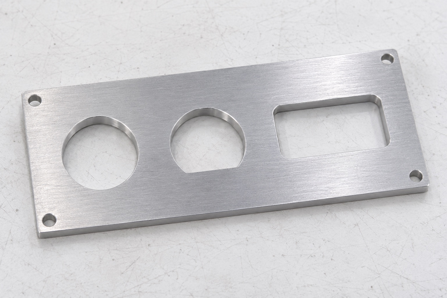
This portable audiometer connector panel is a representative CNC milling case, not a customer delivery or an approved accessory for a named diagnostic instrument. It considers a 6061 aluminum plate with connector cutouts and fastening features. The case explains a proposed manufacturing and inspection route that a real order would need to define. No customer, certification, achieved tolerance, electrical result or acoustic performance is claimed. No working instrument is modified. The panel's geometric acceptance remains separate from hearing-test calibration, signal quality, electrical safety and the approval of the complete enclosure and wiring system for its intended medical application.

Component arrangement under review
The generic panel has a mounting face, a set of circular openings, one anti-rotation detail and a rectangular opening. Fastening holes relate the plate to a separately specified enclosure interface. Exact opening construction, spacing, thickness and corner conditions must come from a controlled model and drawing. The images do not prescribe a connector family, wiring arrangement or commercial device interface. The engineering question is how to keep local profiles and their pattern in the correct relation to the mounting references, while leaving the defined rear envelope clear. That is a specific mechanical task rather than a claim that the panel alone establishes instrument function.
Requirements needed before quotation
The design package would specify alloy and temper, stock form, quantity, datum scheme, front and rear orientation, opening geometry and final finish. Inspection deliverables and any inert envelope comparison belong in the agreed scope. The owner should identify separate connector and hardware interfaces rather than expecting the supplier to select them from a picture. Where a rectangular corner or keyed transition cannot be produced or measured as proposed, resolve the issue before release. A quotation for generic geometry does not authorize changes to an operating audiometer. A real order needs the approved revision and clear acceptance criteria for the actual component and any assembly work included.
Material identity and process condition
The proposed route starts with traceable 6061 stock in the required condition. The blank retains suitable allowance for support, face preparation and final cutouts. Material and revision identity remain connected through machining, treatment and packaging. A suggested substitution needs review. If a finish follows milling, the plan states which dimensions apply afterward and which intermediate checks are needed. This case does not claim a delivered coating, certificate or verified production process. It describes the records that actual work would need. A uniform silver or colored surface cannot establish material identity, electrical bonding, shielding or environmental suitability without the corresponding approved requirements and evidence.
Establishing the mounting face and orientation
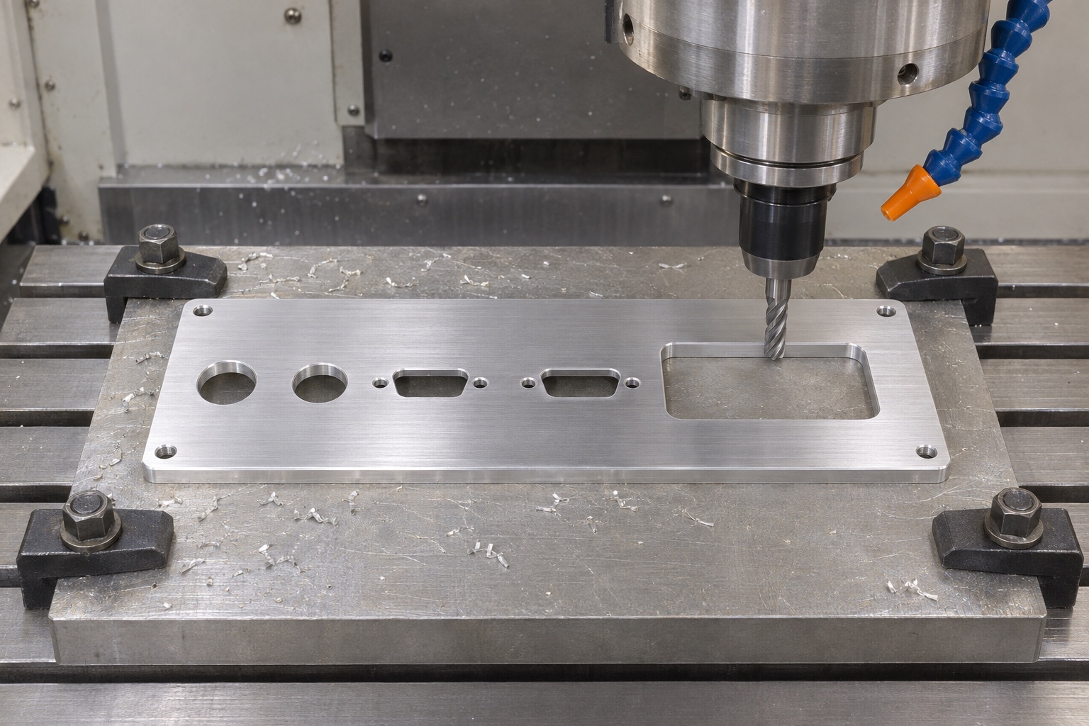
A first stage would prepare or qualify the mounting reference and the features used to locate the panel through later operations. The setup sheet identifies which face is front and how angular orientation is controlled. This is important when a keyed opening or pattern is not symmetric. The inspector should not have to infer handedness from a sample assembly. If the plate is reversed, the plan recovers the same reference structure rather than switching to a convenient edge. It also distinguishes the clamped machining condition from any free or defined mounted state required for acceptance, especially where the final plate has thin sections.
Roughing and producing the cutout pattern
The proposed milling route removes material with adequate support and preserves useful mounting references. Openings can reduce local stiffness, so clamp contact and tool exit clearance need review as the part approaches its final form. The route identifies how related openings share a reproducible positional reference. It does not claim that one setup eliminates all error or prescribe universal cutting parameters. The actual stock, tooling and geometry control the process selection. A clear plan also states which surfaces remain to be finished after transfer and how the rear side will be accessed without damaging the already completed front seating regions.
Finishing keyed profiles and corners
The anti-rotation flat, curved opening regions and rectangular corners are treated as distinct local geometry. Their useful wall length and angular relationship need specification. A rotating cutter creates an internal radius, so the drawing must permit it or define another approved route. The supplier must not widen the whole profile to clear an unreviewed connector sample. Entry and exit finishing should remove prohibited raised material without shortening a functional flat or changing flange seating. The example claims no achieved fit or edge result. Actual acceptance would need the approved requirement and observations made after the final geometry-affecting operations.
Proposed first-article inspection
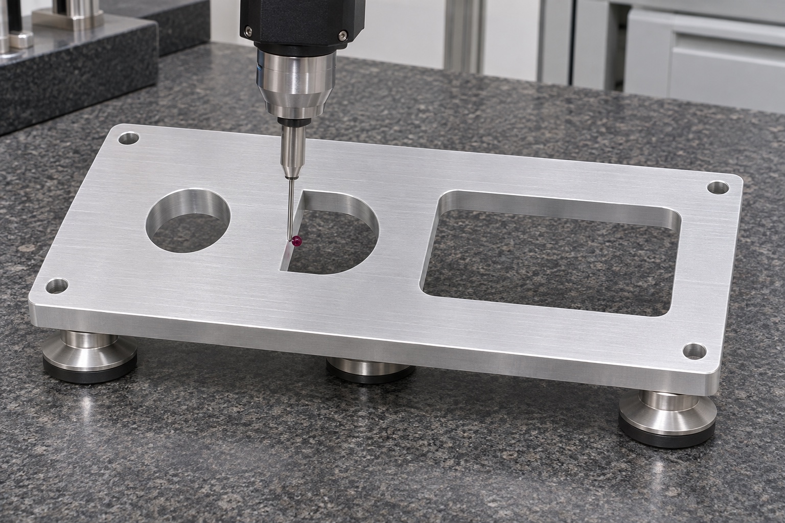
The inspection list would identify mounting references, opening pattern, local sizes, angular details and relevant face and thickness requirements. It would document support, measurement stage and the actual regions evaluated. Coordinate, optical or other suitable techniques depend on access and the required characteristic. A correct circle size does not establish its position, and a correct pattern does not prove each anti-rotation feature. No measured results are included here. A real first-article record would link each observation to part identity, drawing revision, material requirement and final process state, while clearly distinguishing dimensional evidence from a separate bench fit or visual examination.
Defined rear-envelope comparison
After dimensional checks, an engineering fixture could position the panel and identified inert connector references to observe seating and rear clearance. The procedure would record the rear body, retention and other envelopes actually included. No electrical connection, patient test or operating audiometer is used. A mock connector entering the cutout can reveal a local interference, but it does not establish signal integrity, calibration or enclosure approval. The example keeps this observation separate from the component measurements so its limited meaning remains clear. Any broader assembly or electrical conclusion would need the responsible owner's actual design and controlled verification evidence.
A possible interference and review decision
Suppose an inert connector reference enters the opening but does not seat against the intended face. The next review would examine orientation, keyed geometry, local edges, wall thickness and the rear envelope, along with reference identity. It would preserve the contact observation before choosing a correction. Enlarging every cutout is not an appropriate automatic remedy. This scenario is a decision example, not an observed production defect or successful repair. Approved rework would identify affected characteristics and repeat their inspection, followed by the same defined comparison. Changes in fixture or reference must be recorded so the observations remain reproducible and attributable to the actual conditions.
Finish protection and record continuity
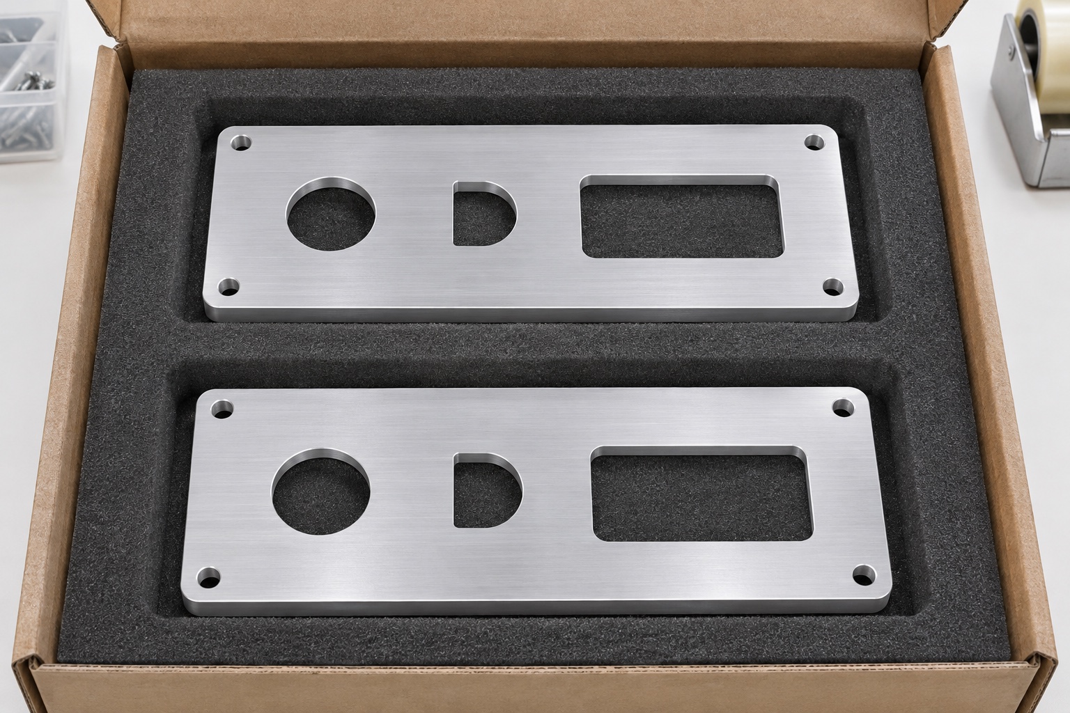
The packaging proposal separates panels and protects opening edges, mounting faces and narrow webs from impact or bending. Contact materials, wrapping and marking follow the actual handling specification. Identity stays connected with material, treatment and inspection records without an uncontrolled mark on a functional seat. Ordinary protective packing does not establish sterile delivery, electrical qualification or a defined cleanliness level. Those requirements need separate processes and acceptance evidence where applicable. The receiving team should be able to identify the right revision and repeat the dimensional checks without first finding transport damage or confusion among similar panels built to different connector patterns.
Developing the example into an order
Provide the final model and drawing, material condition, quantity, final finish, local opening details, front and rear orientation, references and inspection deliverables. Identify the approved connector envelopes and whether their bench comparison is included. Resolve tool and measurement access before accepting a critical characteristic that cannot be verified. Agree first-article review and handling of revisions before a larger batch proceeds. The representative case offers a proposed route and evidence structure, not an interface selected for a commercial instrument. It does not replace a released component design, actual measurements or the separate evaluation required for a complete diagnostic audio system.
FAQ
Is this a delivered audiometer panel?
No. It is a representative manufacturing example without customer delivery data, achieved dimensional results or claims about an operating instrument.
Can the images select a connector model?
No. Connector identity, interface and rear envelope must be supplied in the approved design package. A photograph cannot establish compatibility.
Why distinguish local cutouts from the pattern?
Each opening's size and keyed shape differ from its position and orientation in the panel. Both sets of requirements need appropriate inspection.
Does anodizing prove shielding or bonding?
No. Surface appearance or treatment name does not establish electrical performance. Actual requirements and evidence must come from the system design.
Can the inert comparison verify hearing-test accuracy?
No. It addresses selected mechanical relationships only, not acoustic calibration, signal performance or approval of a medical instrument.
What should happen if a reference does not seat?
Preserve the observation and inspect orientation, edges, keyed geometry, thickness and rear interference before approving any correction and repeating affected checks.

tanghangyun@oemach.com