
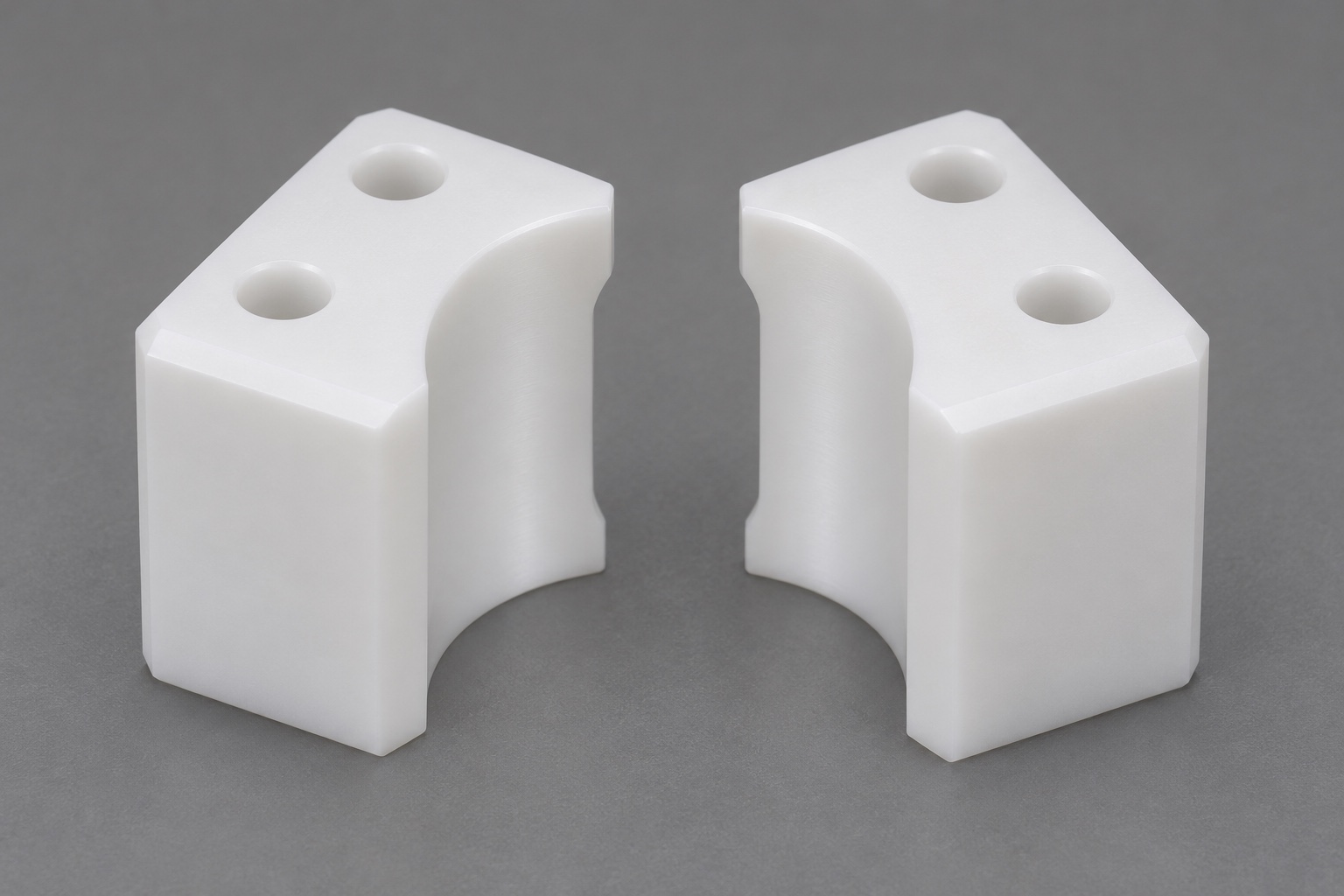
Representative example rather than a delivery claim
These POM-C tube decapper jaw inserts are a representative CNC machining example, not an actual customer delivery or a qualified production design. The case considers two polymer blocks with opposed concave faces and defined mounting references. It follows the proposed manufacturing and inspection decisions that a real order would need to document. No customer identity, certification, measured capability or decapping result is claimed. The example uses no real specimen and does not establish removal torque, retention or tube compatibility. It addresses component geometry separately from an automated medical laboratory process and from the approval of equipment used to handle samples.

The generic interface under review
Each insert has a mounting seat, fastener features and a concave contact region. The pair is shown opposite an open gap, but the final drawing must identify whether the intended contact is with a cap, tube body or another specified reference. Those choices change the actual interface requirements. Images cannot establish a usable tube size or an approved contact pattern. For this discussion, the geometry remains smooth and generic, without adding teeth or texture to imply grip performance. The manufacturing review asks how the contact region is located relative to the mounting references and how that relationship can be inspected.
Inputs a real quotation would require
The initial package would include a controlled drawing and model, POM-C material specification, quantity, left and right definitions where relevant, surface requirements and inspection deliverables. It would identify the actual mounting and locating features rather than assuming the fasteners do both jobs. The owner should state whether inserts must be paired or interchangeable and which assembly checks are required. Any unresolved chemical exposure, cleaning or handling requirement must be clarified before release. The example does not supply those application inputs. A quote for generic geometry is not permission to select contact dimensions for an operating laboratory instrument.
Stock preparation and revision identity
The proposed route begins with identified POM-C stock of the specified grade. Stock form and allowance should permit stable support through milling without creating unnecessary thin regions before they are needed. Material identity remains connected to the parts through preparation and finishing. If several similar insert sizes are produced, their revisions and intended orientation must not become mixed. A supplier proposal to change material or processing history requires review. This case does not assert that a particular stock was qualified or that a production batch was made; it describes the traceability and planning information a real order would need.
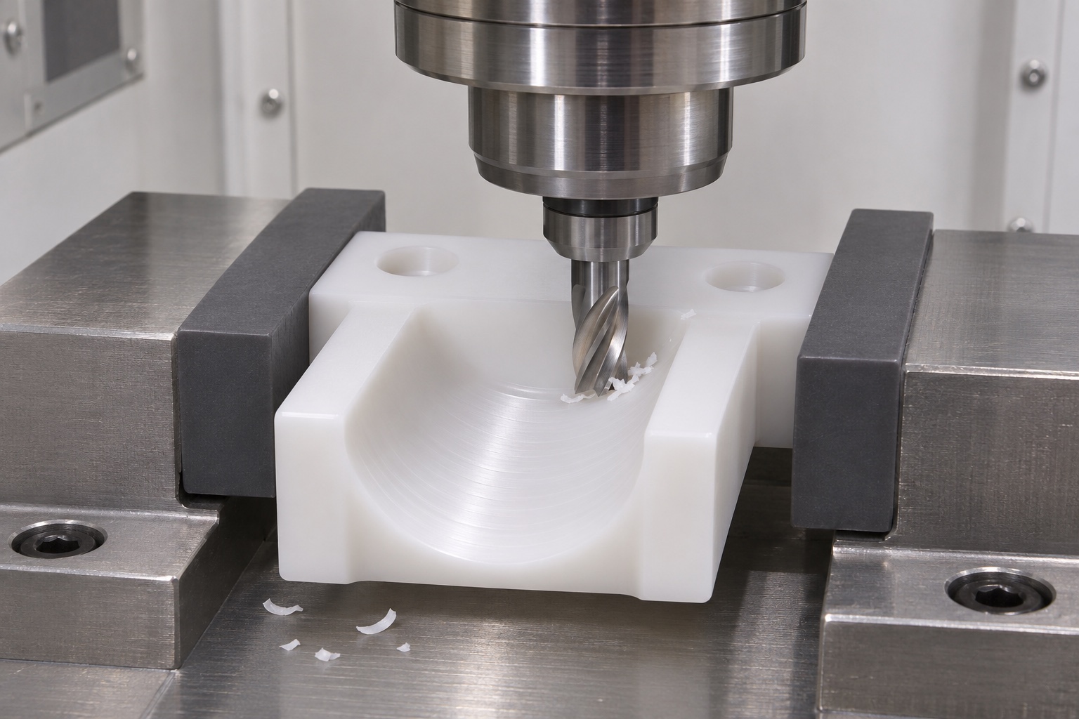
Establishing the mounting surfaces
A first machining stage would prepare the reference seat and any locating shoulder used by the drawing. The setup should show how the insert rests and where the clamp applies force. It must leave access to the features required by the next operation. An operator should not have to choose a different convenient reference for every part. If the block will later be inspected in a mounted condition, that condition needs a defined fixture rather than an arbitrary screw tightening trial. The route also considers free-state measurements so clamping distortion is not mistaken for the component geometry that the receiving team will evaluate.
Milling the concave contact region
The proposed milling sequence roughs and finishes the contact profile while preserving the relationship to the mounting references. The cutter and support are selected for the actual grade, section thickness and access. A narrow remaining edge should not be treated as though it has the stiffness of the starting block. If the part is transferred between setups, the process sheet identifies how the original reference is recovered. No achieved radius, surface roughness or tolerance is claimed here. The process must be reviewed against the released requirement and supported by the actual inspection method, rather than by a broad statement that polymer machining is precise.
Finishing fastening features and edges
Fastening holes, recesses and any locating features are treated as separate characteristics. A counterbore that accepts a screw head does not demonstrate that the contact profile is correctly positioned. The edge condition should remove prohibited raised material without changing the useful contact region. Tool access to local corners and thin sections is reviewed before choosing the finishing method. After any operation that may alter geometry, the affected characteristics would be checked again. If a local region cannot be reached or measured as proposed, the issue should return to engineering review instead of being silently accepted through a passing assembly observation.
Proposed individual-part inspection
The first-article plan would record the mounting seat, locating features, hole pattern and the contact profile's size, position and orientation as required by the actual drawing. It would identify the support and measurement condition for the polymer insert. A suitable optical or low-force contact method may be considered, but its applicability depends on the characteristic and access. No measured results are included in this representative case. A real report would connect observations to part identity, stock requirements and drawing revision, and would distinguish characteristics measured on the separate insert from those evaluated only after mounting a pair.
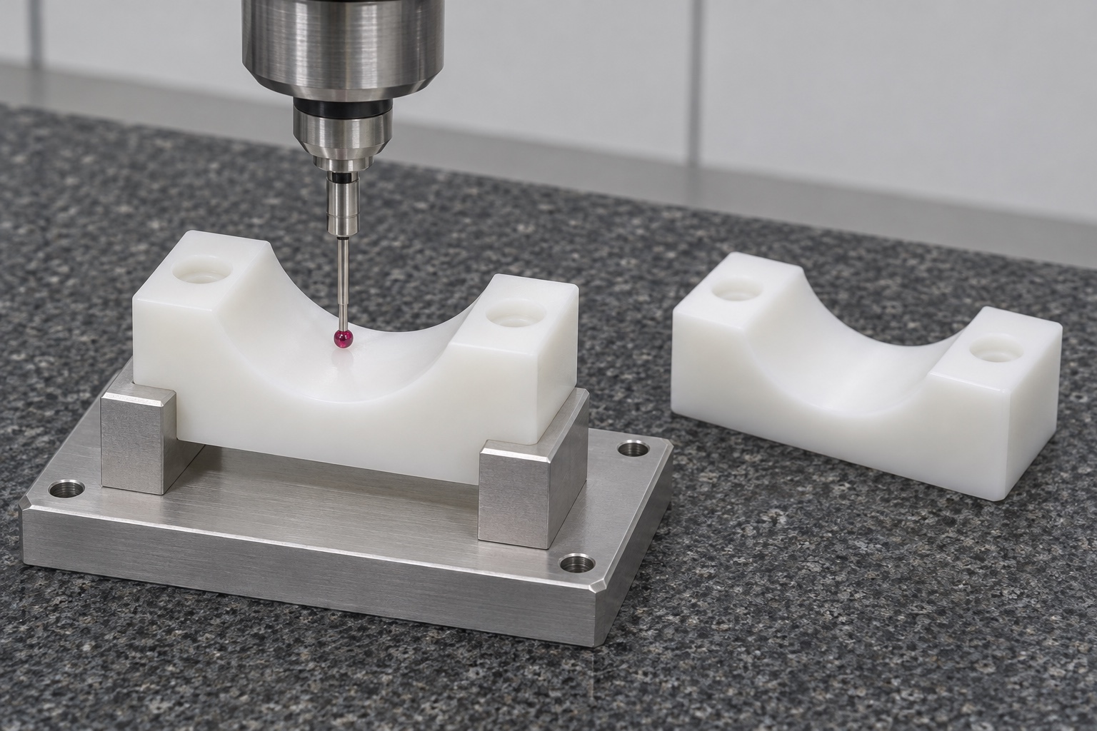
Proposed pair comparison
After individual inspection, an inert fixture could position two identified inserts and an agreed reference to examine contact location and approach clearance without applying a production gripping load. The procedure would define support, orientation and the positions observed. No specimen tube or biological material is used. A dry contact observation may help identify a geometric discrepancy under that setup, but it is not evidence of cap-removal torque, reliable retention or specimen safety. The example deliberately keeps this observation separate from the component measurements and from any validation of an automated decapping process on actual equipment.
Review path for uneven seating
Consider a bench observation in which one insert contacts the reference before the other. The next review would compare mounting-seat condition, orientation, profile position, reference identity and carrier alignment. The team would preserve the observation before choosing an action. Automatically deepening both grooves is not an acceptable substitute for finding the cause. This is a decision example, not a claim that a production defect occurred or was corrected. Any permitted rework would require a documented disposition and repeat inspection of affected dimensions, followed by the same controlled pair comparison with identified references and recorded support conditions.
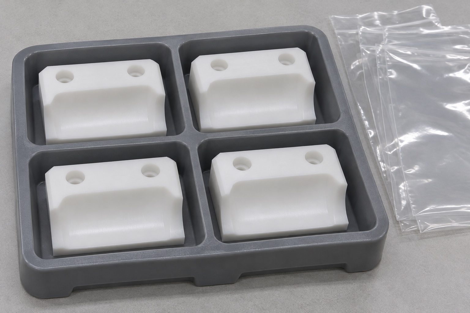
Packing and identification proposal
The packing proposal separates inserts and protects their concave profiles and thin edges from contact damage. It avoids an uncontrolled load on the contact region and preserves pair or orientation identity where specified. Any bag, insert or marking material must meet the actual handling requirements rather than being selected solely for appearance. Ordinary protection in transit does not establish sterility, reagent compatibility or a validated cleanliness level. Those requirements need separate specifications and acceptance evidence. The receiving team should be able to find the correct revision and inspection record without relying on a shape comparison between visually similar polymer blocks.
Requirements for a real manufacturing order
To develop the example into an order, provide the approved interface definition, drawing, POM-C grade, quantity, surface condition and inspection list. State the intended contact object, the mounting references, whether pairing is required and which unloaded checks belong in the deliverables. Resolve any support or measurement concern before accepting a critical characteristic that cannot be verified. Agree the review process for first-article findings and design revisions before a larger batch proceeds. The example offers a proposed route and evidence structure; it does not replace a production specification, actual dimensional results or validation of the medical laboratory workflow.
FAQ
Is this an actual tube decapper delivery?
No. It is a representative machining example and contains no verified customer delivery, measured production result or equipment performance claim.
Can the images determine a supported tube size?
No. The intended interface and dimensions must come from an approved drawing. The images do not establish compatibility with a tube or cap.
Are smooth inserts equivalent to textured gripping jaws?
No. Texture or teeth change the design and its requirements. They must be specified and reviewed rather than added by the machining supplier.
What would be inspected before comparing the pair?
The actual drawing controls the list. This example discusses mounting seats, locating features, fastener geometry and each contact profile's relationship to its references.
Can the unloaded pair check qualify cap removal?
No. It addresses selected geometry with inert references. Torque, retention, sample integrity and automated process approval require separate evidence.
What should happen if one insert contacts early?
Preserve the observation and inspect references, mounting conditions and profile geometry before choosing an approved correction and repeating the relevant checks.

tanghangyun@oemach.com