
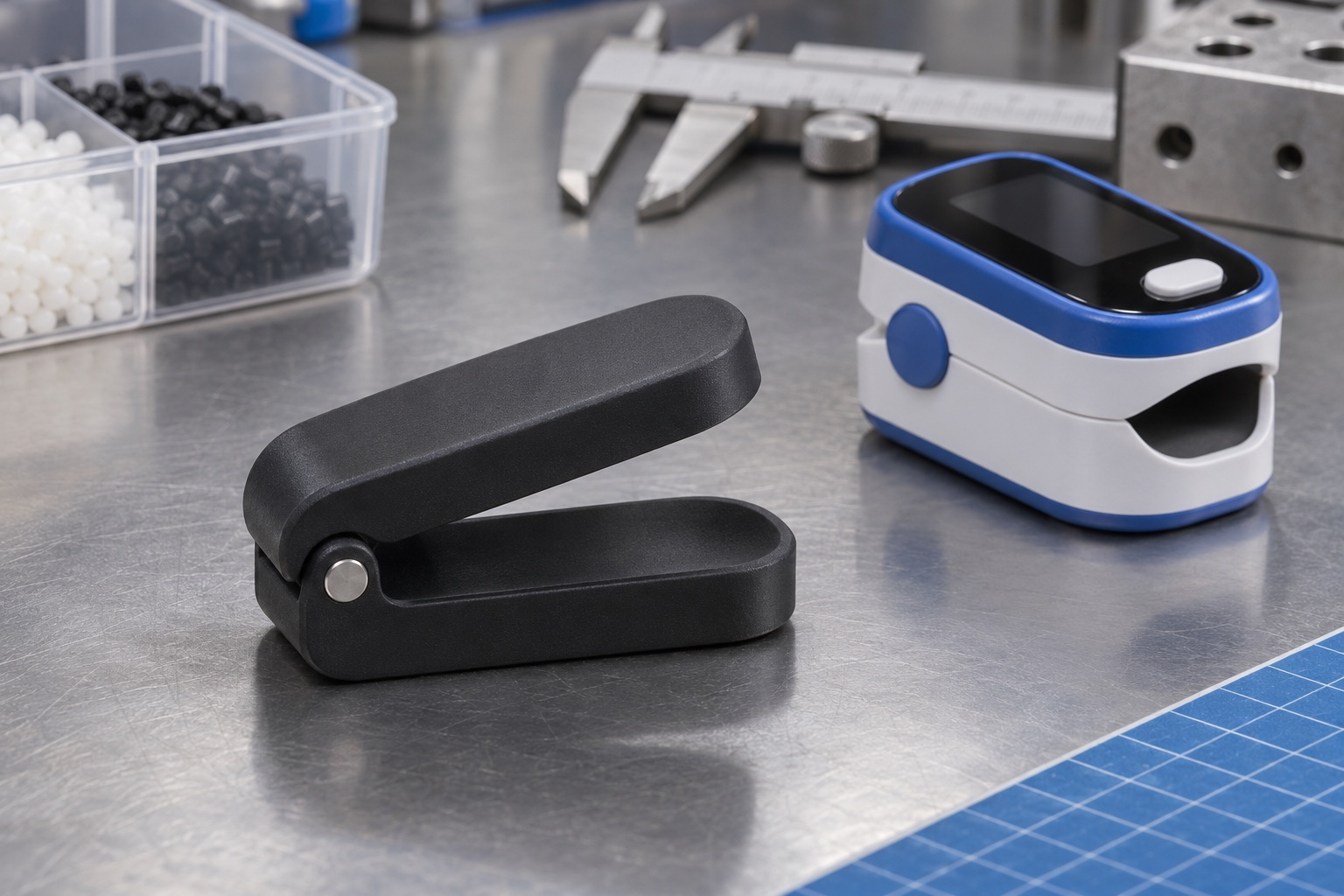
Set the scope of the demonstration
This representative CNC example considers two short rounded POM-C jaws with a transverse hinge pin at one end. The upper jaw is shown slightly open to illustrate the geometry. There are no electronics, optics, batteries or springs in the example. It is not a shipped customer part, a working pulse oximeter, a replacement enclosure or a verified test result. The illustrations describe a non-clinical mechanical layout, not approved manufacturing drawings or instructions for using a medical device. No part of the proposed trial involves a person or a functioning instrument.

Identify the two jaw references
The drawing would establish a base or side reference on each jaw and locate its pin bore from that system. The outside radii do not necessarily control assembly position. Specify which hinge surfaces may touch and which neighboring faces must clear each other. If one jaw includes a feature that limits motion, define it independently of the rounded outer profile. Establish an orientation scheme before inspection so left and right bore entrances are not confused. The approved bench drawing must identify the mating parts and which side is viewed during each check.
Specify the pin separately from the jaw
The pin diameter, material, retention and working length would be controlled separately. The concept does not supply a pin fit or a retention method for an operating device. Define whether the bench pin is fixed or free to rotate, and which contacts count for acceptance. A pin that can be inserted may still show play or interference during movement. Record the actual reference used rather than changing pins to make a trial pass. If the drawing requires alignment under a particular support condition, carry that condition into the fit record.
Capture material identity before machining
The proposed jaw material is black POM-C, with grade, stock form and documentation to be stated on a real order. Color does not identify the polymer or its chemical, electrical or medical suitability. Capture the lot before machining and preserve that identity on the inspection record. An approved finish or insert would be a separate drawing requirement. Identify any changes to the final measurement state after assembly or handling. The pictures do not establish material certification, compatibility with patient contact or validation of cleaning, wear or durability.
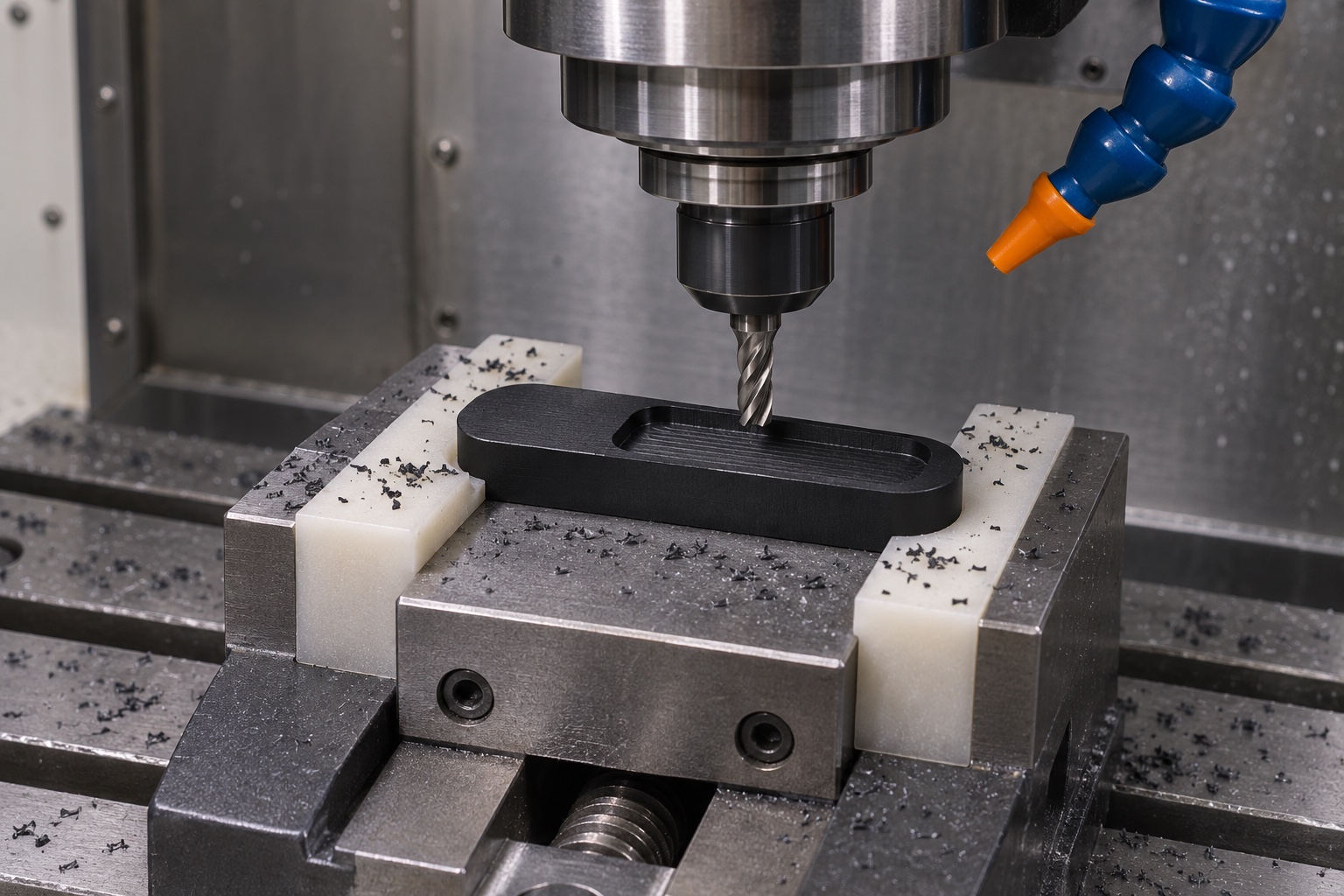
Establish stable stock before cutting hinge details
A candidate route faces stable references, roughs the outline and leaves enough material around the hinge to support subsequent work. Avoid gripping the thinnest region during cutting. Release the stock and assess movement before finishing if the intended tolerances require it. The CNC image is an illustration of access, not an approved production process. The actual tool, stock orientation, cuts and support would be reviewed against the released drawing. If a separate setup is needed for the transverse bore, specify how the location and direction of the axis are transferred.
Finish profiles and bores in a defined condition
Finish the outer profiles and the usable bore regions as the drawing requires. Protect the bearing length when breaking an edge. Check that a corner or relief does not interfere when the jaws move through the defined unloaded bench range. Do not polish the inside faces indiscriminately to eliminate a witness mark. Measure the functional areas before any approved change and remeasure those affected. If the sample is measured while held, record the support and consider whether the free part will differ. A stable reading under a clamp does not establish free-state geometry.
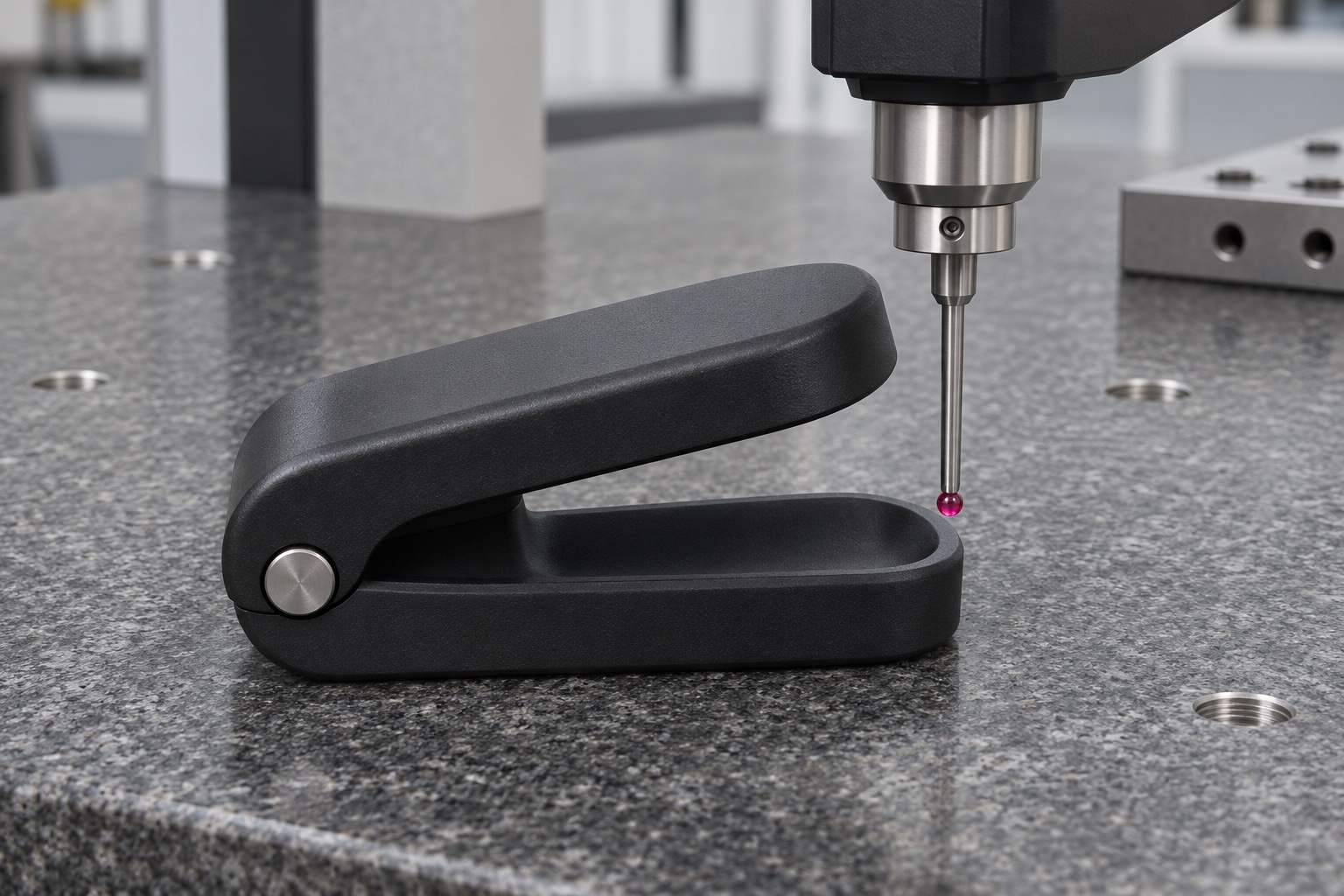
Measure the jaw and bore relationships
An example report would identify the drawing revision, measuring zones, instrument and support. The two bores would be checked for the required individual dimensions and related to their jaw datums. The trial pin can be checked separately. A measurement at the chamfer does not represent the usable bore, and a fit with an unknown pin cannot establish size. No values or conformity results are shown by the illustrative inspection scene. Any acceptance decision would require the actual part, controlled measurements and the drawing's applicable limits.
Compare the assembled mockup without a spring
Use only the identified parts and reference pin on the bench. Observe whether the pin enters without forcing and whether the two jaws move through the agreed unloaded range without unintended contact. Record the angle or location where resistance appears using the method defined for the trial. If the mockup is disassembled, preserve the orientation and identities for a repeat. The observation does not establish strength, fatigue, opening force, clip pressure, optical performance or suitability for use on a finger. It is limited to mechanical geometry in that setup.
Diagnose one discrepancy at a time
If the assembly binds, first check the pin and drawing revisions, then inspect bore entry, debris and support. A bind present only after rotation may originate at a jaw profile rather than inside the bore. Compare the separate part measurements with the observed contact. Do not enlarge multiple features before understanding the source. If an authorized correction is made, preserve the original findings and repeat the same checks with the same documented setup where practical. This lets a second reviewer distinguish a geometry correction from a change in reference or handling.
Clean and identify the parts for receiving
Remove loose machining residue under the agreed shop method and inspect the bores, hinge surfaces and seating references afterward. Keep any marking or label outside the contacts. Record material lot, revision and pairing if the trial depends on matched parts. A surface that looks clean is not evidence of a validated clinical cleaning process, sterilization or resistance to a disinfectant. Handling a nonfunctional development sample is different from maintaining an operating instrument. Any requirements for the actual device remain separate and are not prescribed by this example.
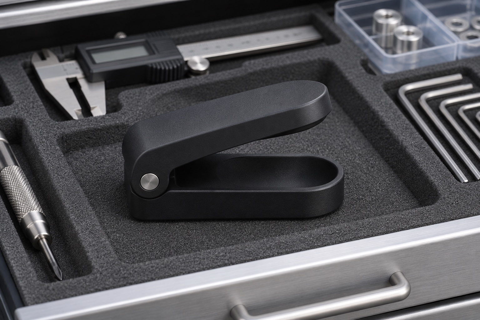
Pack the jaws and pin without damaging edges
A fitted insert can hold the parts on robust exterior surfaces while leaving the bore entries clear. Keep the pin in an independent pocket and label the parts so their relationship is preserved. At receipt, check the packaging and contact regions for movement, impact and debris. Repeat any measurements affected by visible damage. The illustration shows ordinary mechanical protection only, not sterile delivery, a cleanroom classification or a validated shelf life. Keep the measurement report and bench setup instructions with the revision so the recipient can reproduce the same comparison.
Define the evidence for a real order
An actual order would require controlled part drawings, pin definition, material and finish, inspection states and a permitted bench motion. The shop could report the geometry and separate unloaded fit observations within that scope. The responsible device owner would verify any future use in an approved instrument and any patient, optical or electrical performance. No actual delivery, customer identity, certification or measured result is reported. This example shows how to keep a CNC trial focused on bore location, pin fit and clearance without representing it as a clinical device.
Manufacturer background reference: www.nonin.com.
FAQ
Is this a delivered pulse oximeter component?
No. It is a representative CNC example with illustrations, not a customer delivery or an approved replacement component.
What does the transverse pin do?
It forms the mechanical rotation axis in the concept. Its exact fit and retention would be defined on the approved bench drawing.
Why is there no spring?
The example isolates unloaded geometry. It does not address force, retention under load or the behavior of a working instrument.
Can the bench trial be conducted on a person?
No. It is limited to inert references and a nonfunctional assembly, with no clinical or patient use.
Can a smooth bore pass without measurement?
No. Appearance does not establish size, form or position. Follow the controlled inspection plan.
How should the three parts be shipped?
Protect the jaw contacts and pack the pin separately. Preserve each part identity and the revision used in the trial.
tanghangyun@oemach.com