
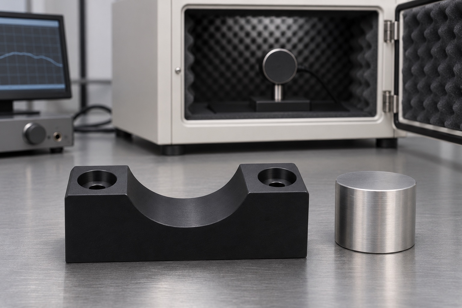
Describe the support and its limits
This representative machining example considers a black POM-C saddle with a shallow transverse cradle and two counterbored retaining holes. It supports the outside of an inert cylinder in a bench demonstration related to hearing instrument test equipment. It does not form a calibrated acoustic cavity or contact an acoustic opening. The part shown is illustrative and was not supplied to a customer. No measurement outcome, calibration, approval or performance claim is reported. The actual drawing would define whether and where a real coupler body can be supported.

Identify where the surrogate can touch
The conceptual support uses a short, smooth cylindrical segment as its contact region. Neighboring connectors, caps and seam details are intentionally outside the supported length. The fixture does not seal the cylinder or act as a retaining clamp. An order would specify permissible contact zones, entry clearance and whether a separate stop locates the cylinder axially. Without those definitions, the cradle can look correct while touching an incompatible feature. Mark intended contacts on the drawing and show clearance to adjacent equipment over the entire insertion and removal path.
Establish the base reference and mounting holes
The bottom face sits on the test plate. The two counterbored holes allow hardware to retain the saddle without heads protruding into the usable contact region. Retention does not establish a precise lateral reference if clearance is present. If the setup needs independent lateral location, identify the reference on the drawing and include it in the bench documentation. Do not assume the fixture lies flat just because it can be tightened. Check whether a burr or debris under the base alters the seated condition before looking for a cradle error.
Trace the material and the final condition
The example proposes black POM-C for a machinable bench component. The released order would specify grade, stock form and the material evidence required, not only the visible color. Document the stock lot and identify the final surface state on the drawing and report. Any coating, bonded pad or insert may change the supported height or contact location. Evaluate such additions independently and include them in the final verification state if approved. The appearance of the illustrated block does not prove material identity, chemical resistance or acoustic performance.
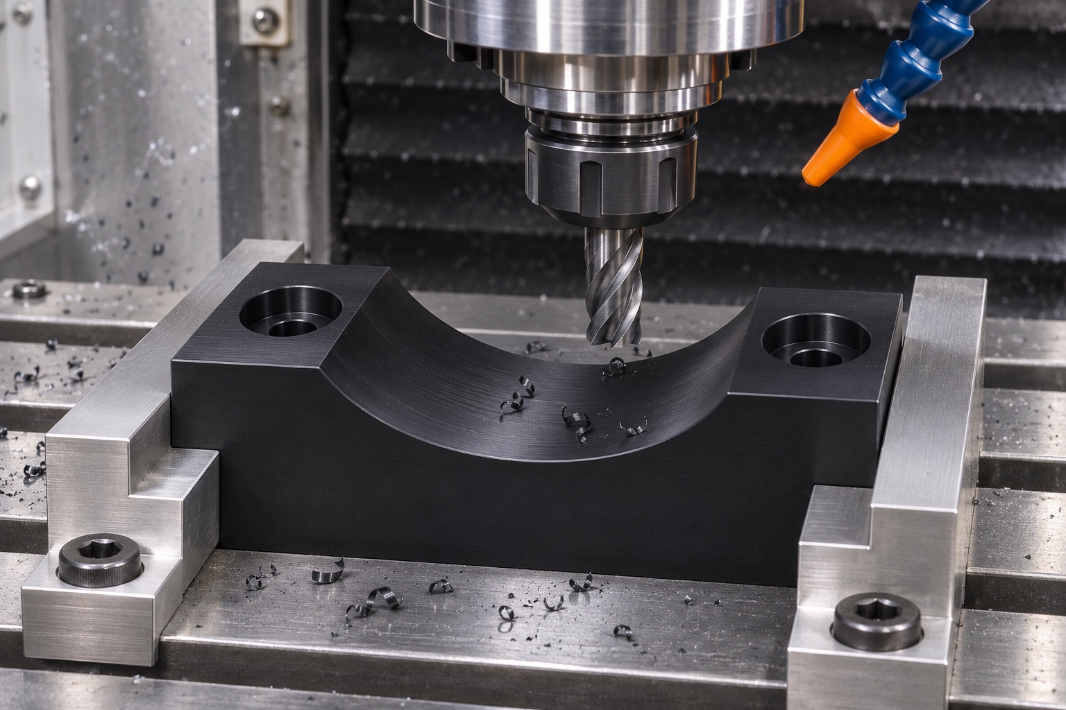
Rough the block before the finish contour
A possible manufacturing route faces the base, establishes side references and roughs the top cradle with allowance for finishing. Support the block on stable surfaces and avoid clamping the edge of a thin wall. If roughing moves the part, inspect the released condition before reestablishing the reference. Select tools based on the actual contour and access, not on the image. The illustration does not supply cutting parameters or a validated toolpath. A trial part would help confirm that chips can escape and the contour can be finished without an unwanted witness ridge.
Finish the cradle and hole seats independently
Finish the curved surface relative to the base and maintain any relief required at its edges. Machine and deburr the counterbore transitions without changing the support contour. Confirm that hardware does not protrude above the designated clearance area. If the drawing requires a stop or a second block, tie its position to the same bench reference rather than estimating the location from the outline. Verify any edge break separately. A transition that appears smooth is not necessarily acceptable if it shortens the available support or changes where the cylinder sits.
Measure the cradle and the master setup
A practical inspection package could include base condition, cradle profile, axis location and hole geometry. Select measuring points inside the usable support area and record any exclusions near edge reliefs. In a second check, seat an identified cylindrical master and record its position relative to the defined base at specified stations. Record the master diameter, part support and measurement method. The master check evaluates seating in that arrangement, not the complete profile on its own. No measured values or conformity judgment are represented by the inspection illustration.
Test the fit with an inert surrogate
An initial bench trial can use an inert cylinder to examine insertion, removal and visible contact. Observe how the surrogate rests after independent reseats and note any variation along the cradle. If the test setup has two supports, confirm that their references agree before comparing height. Avoid pressing a cylinder down to conceal a high edge or burr. Neither the example nor a hypothetical dry trial defines acoustic leakage, sound pressure or device acceptance. An approved acoustic check would be a separate activity controlled by the equipment owner.
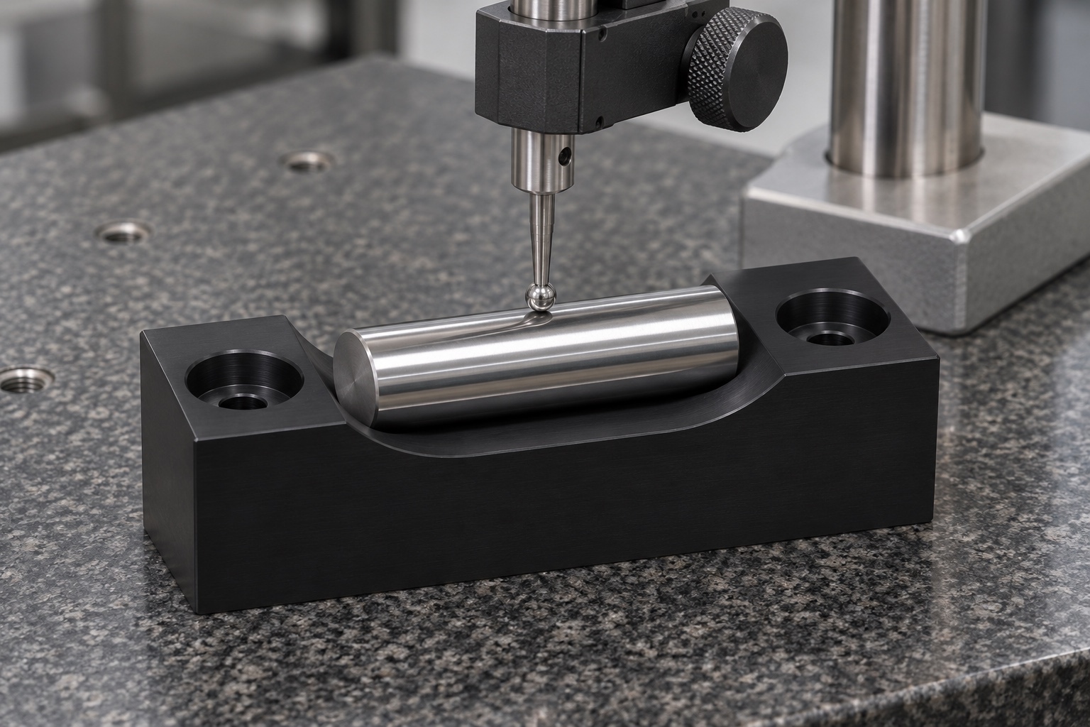
Diagnose a mismatch before altering the cradle
If the cylinder sits higher than expected, check the master diameter, the two contact regions and the test plate before deepening the contour. Look for an interference at an edge, foreign debris or an incorrectly installed screw. Document the original state and any approved correction. If a mating body does not match the intended geometry, changing the saddle may affect other variants; confirm the drawing revision first. Compare measurements and seating observations as separate evidence so a convenient fit after rework does not hide a change to the defined part.
Clean and identify the external fixture
The order would define how loose machining residue is removed and where a lot mark can be placed. Inspect the cradle, counterbores and mounting face after cleaning under agreed criteria. Keep labels, adhesives and rough marks off the functional areas. If the fixture is used near actual test equipment, the equipment owner determines compatible materials and maintenance procedures. The packaging and inspection images do not demonstrate disinfection, sterility or controlled contamination levels. Treat visual cleanliness as an observation unless a validated process and criteria are separately specified.
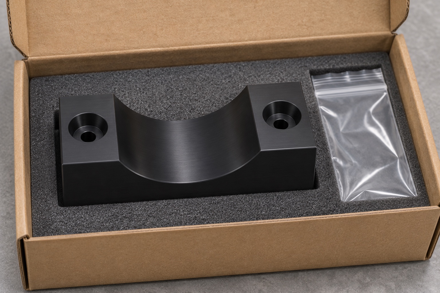
Package without loading the cradle
Support the block at stable exterior surfaces and keep loose screws separate from the curved contact area. A fitted insert can limit movement without deforming the block or abrading the base. Put the revision and lot outside the bag or on an agreed nonfunctional area. At receipt, check the packaging and inspect the mounting plane and cradle before using the fixture. If damage is visible, repeat the specified measurements in the same condition. The illustration shows ordinary protection during transport, not a sterile barrier or storage qualification.
Define what a real order would establish
Send the approved drawing, material grade, surrogate geometry, clearances, support condition and receiving plan. Ask for a geometry report and a separate record of any mechanical fit check. The manufacturer of the complete test system decides whether the saddle may be used in an approved setup, and verifies acoustic performance independently. No end-user delivery, calibration certificate, pass result or customer identity is asserted here. The example shows what a CNC supplier can document about a mechanical saddle while keeping the scope of the evidence clear.
Manufacturer background reference: grason-stadler.com.
FAQ
Is this a delivered or certified component?
No. It is a representative machining example with illustrative images, not a supplied customer part, verified accessory or calibration result.
Does the cradle touch the acoustic port?
No. The concept supports an external cylindrical area and leaves the acoustic path and adjacent connectors outside its function.
What is the purpose of the two counterbores?
They provide clearance for retaining screw heads in the bench fixture concept. Precision registration would require a separately defined locating feature if screw clearance is present.
What does the cylindrical master verify?
It helps compare seating or height in an identified mechanical setup. It does not replace the profile measurement or establish the behavior of another body diameter.
Is this an acoustic calibration procedure?
No. The example covers manufacturing and bench fit. The approved acoustic measurement configuration and procedures belong to the equipment owner.
How should the part be packed?
Keep other parts and loose hardware away from the cradle, support the exterior and identify the lot and revision. Inspect the block if the package shows signs of movement or impact.

tanghangyun@oemach.com