
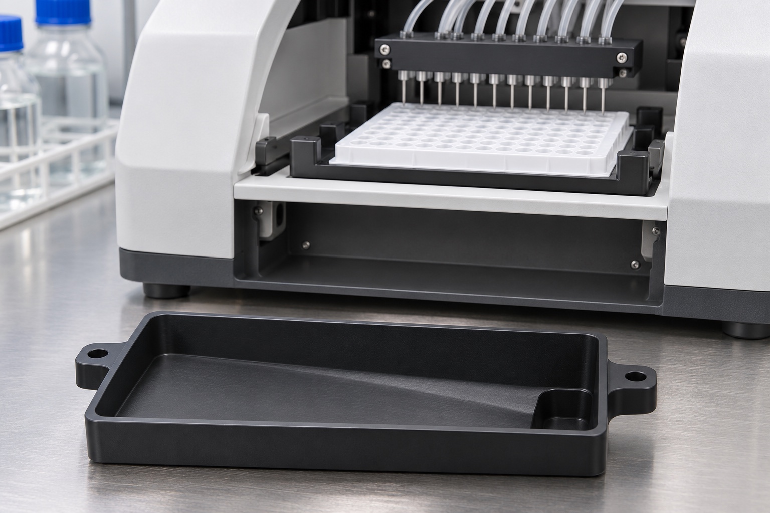
Define a secondary collection concept
This representative CNC example considers a removable black polypropylene tray for incidental drips in a generic bench microplate washer concept. It has a rectangular rim, one sloping shallow cavity, a low corner pocket and two exterior support ears. The part is not a primary waste container or a drain fitting. No real customer delivery, device certification, collection capacity or validated spill performance is reported. The images are illustrations to communicate a manufacturing and inspection approach, not evidence of a deployed product.

Establish the rail seat and clearance conditions
Two test rails support the exterior ears and define the installed orientation. The tray should not accidentally rest on the cavity bottom or on a nearby panel. The released assembly would specify how far the tray can move before contacting a stop and how a user can remove it without an unintended tilt. Record both the nominal orientation and any permitted installation variation. The low pocket is a collection point in the example and has no through drain, connector or implied seal.
Select an actual stock grade
Black polypropylene is a proposed prototype material. A drawing and purchase order would define its exact grade, stock thickness, lot documentation and any relevant restrictions. Color is not proof of resin identity or chemical resistance. Compare the proposed resin with the liquids, temperature, cleaning and storage requirements provided by the owner. If the tray is to be exposed to an actual waste stream, the system owner must determine the appropriate testing and handling precautions. The illustration cannot be used to choose a compatible resin.
Rough the cavity while the part is rigid
One possible machining sequence faces the underside, roughs the profile and opens the pocket while material remains around the rim. Use stable supports and leave finishing allowance on the cavity and seating regions. Plastic chips should be cleared without dragging a cutter through accumulated material. A trial part can be released to check movement before the finish pass. The generated machining view describes the type of work; it does not prescribe feed, cutter, clamping force or a validated process window.
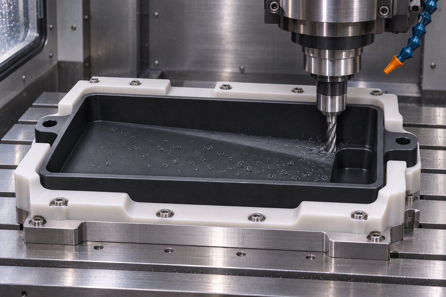
Finish the slope and corner pocket separately
Finish the floor relative to the designated support references and transition into the low pocket without leaving a raised ridge that blocks the intended flow. The corner radius should accommodate the chosen tool and intended access. Check whether the floor retains enough material after the lowest region is cut. A dimension on the outside does not substitute for residual wall thickness where it is critical. If inspection cannot reach a part of the transition, clarify the method or adjust the design before production.
Finish the ears and remove burrs from the rim
The ears must seat reproducibly on the defined rails. Finish their contact surfaces to the drawing and distinguish them from any exterior shapes used only for handling. Inspect the top rim for tool witness ridges or loose strands left after milling. Avoid rounding the functional edge after the final dimensional report unless the change is allowed and rechecked. If the tray is held by clips, verify the intended clip clearance on the approved fixture rather than assuming the ears alone establish retention.
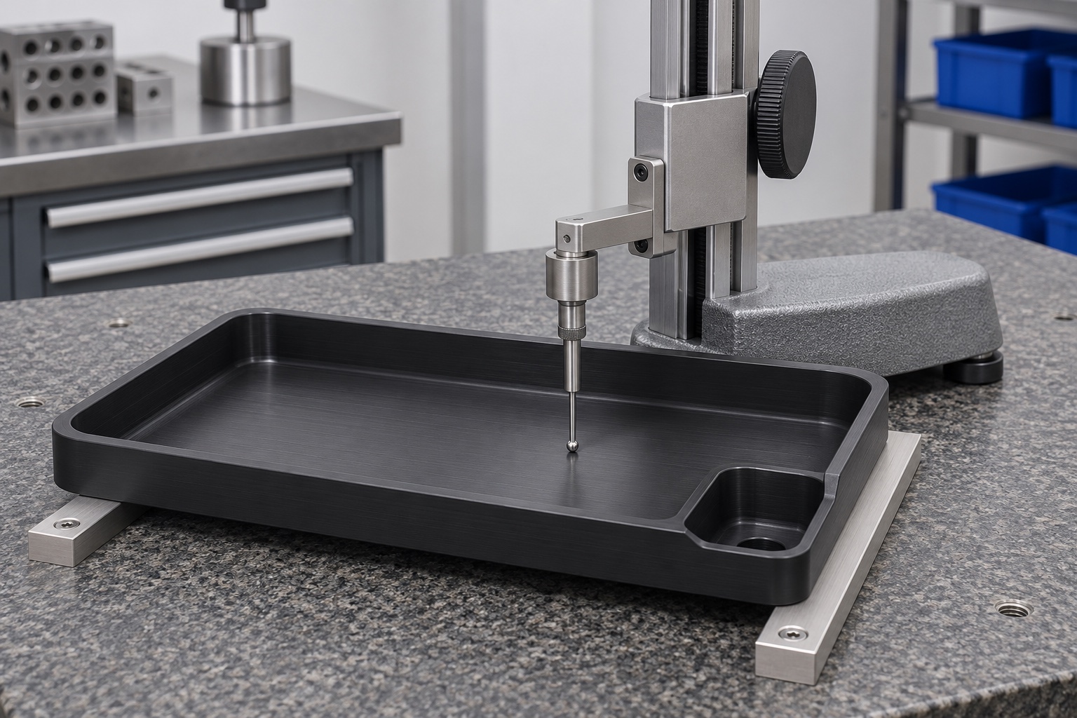
Inspect the tray on a representative support
Use a defined fixture to measure the floor at several stations and verify where the collection pocket is low relative to the rim and rail plane. Measure support ear positions and the outside envelope as separate characteristics. Select a probing approach that does not visibly deflect the tray and report the method. A free-state measurement can help identify distortion, but the installed orientation matters for collection. The illustrated inspection shows no recorded value and must not be interpreted as a passing report.
A useful receiving fixture can be much simpler than the washer. It may need only two identified rails, an orientation stop and sufficient access for a height indicator. The stop should not lift the tray or pinch the support ears. Mark the same measurement locations on the supplier sketch and the receiving record. If results differ, compare the rail heights and check for debris before attributing the difference to the cavity. Where a fixture is intentionally different from the installation, record that limitation so its results are not mistaken for device acceptance.
Check collection with a safe surrogate
A bench trial could apply a safe surrogate liquid at predefined locations, while watching where it travels under the nominal and agreed off-level conditions. The test record would state the amount, application points and support state. Photograph or record unexpected standing liquid rather than dismissing it as cosmetic. Keep removal handling separate: a liquid that stays contained when the tray is seated can move during extraction. This example reports no test and does not define real waste handling, chemical compatibility or an allowable overflow condition.
Resolve cleaning and inspection access
Confirm that the design owner can see and access the low pocket using its approved procedure. Do not assume a dark surface makes residue easy to detect. An internal corner that is acceptable for milling can still trap debris and may need a revised radius or an alternate inspection approach. Before packaging, remove loose chips and inspect the floor, pocket and seating surfaces. Keep the approved receiving cleanliness level distinct from any in-service decontamination procedure, and do not claim sterilization or disinfection based on appearance.
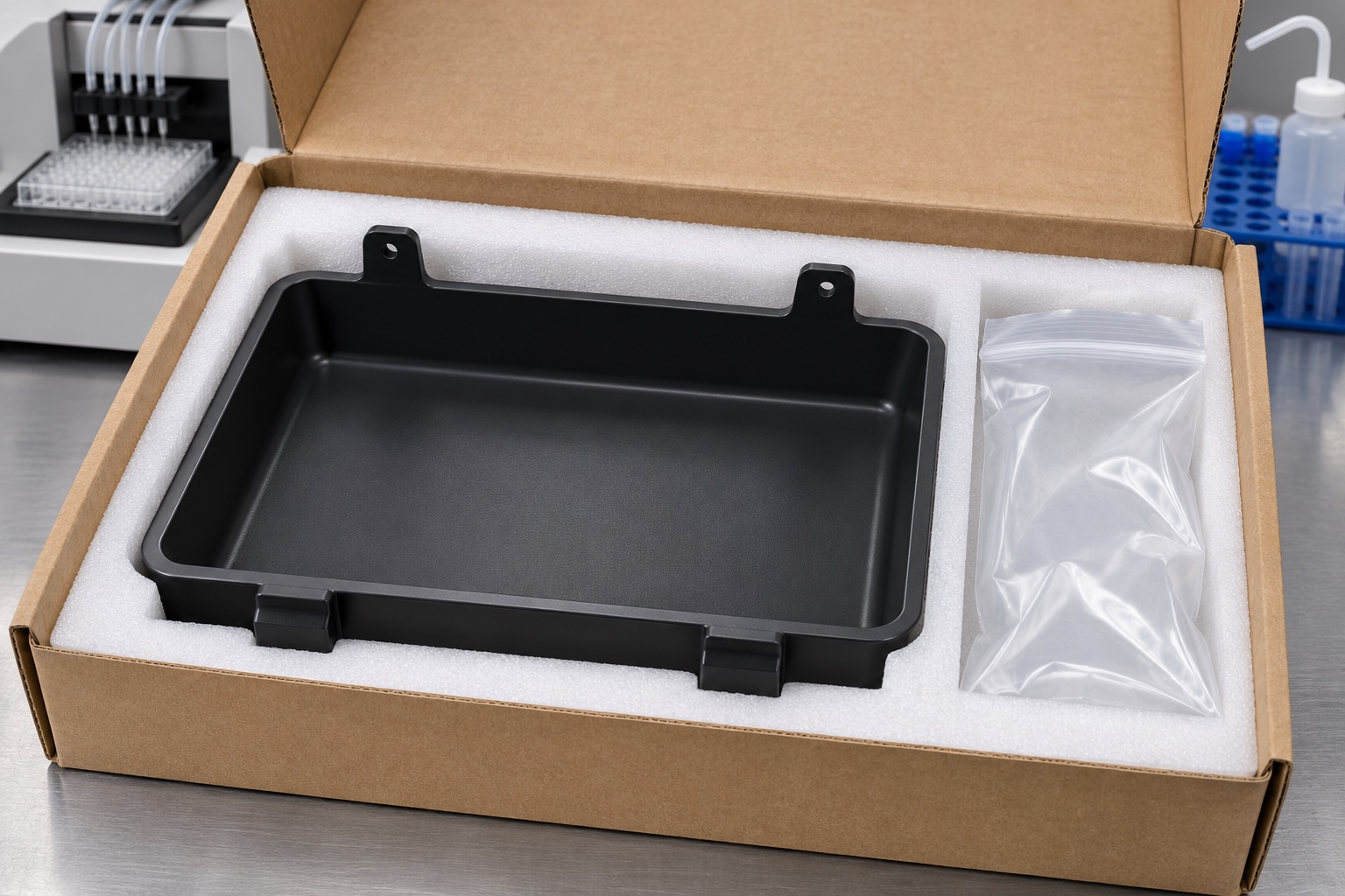
Package from the outside, not the cavity
Use a fitted insert or independent supports that engage robust exterior regions without pressing the floor out of shape. Keep abrasive packing material, tape and hardware out of the basin. Mark part revision and material lot on the external package or an agreed nonfunctional area. On receipt, review the support ears and rim for compressed packaging or marks before repeating the dimensional and dry-fit checks. The concept uses ordinary protective packaging, with no sterile barrier, controlled environment or storage-life claim.
Separate the reports for design decisions
A sample report would state drawing conformance, observation from a dry mechanical fit and, when authorized, observations from a safe bench liquid trial. Keep them as distinct records with the same revision and lot identifier. If the installed geometry differs from the trial setup, do not carry the observed collection behavior into the device claim. Similarly, do not change the floor or add an outlet without approval. A proposed correction should be evaluated with the owner against the same reference conditions used for the first sample.
List what a real order still needs
The order should define the drawing, exact stock grade, rail reference, usable clearances, inspection checkpoints and packaging. The equipment owner defines collection and removal conditions, exposure limits and the role of any waste monitoring. Record open items instead of treating an illustrative tray as a released device component. This division makes the machining evidence useful without adding a fictitious customer, certification or result. It also gives the receiving team a way to repeat the support and inspection checks on actual parts.
Manufacturer background reference: www.tecan.com.
FAQ
Is this a delivered washer component?
No. It is a representative CNC machining example. No actual order, supplier qualification, measured spill test or field performance is reported.
Why is the low pocket not shown with a drain?
The concept is a removable collection tray. An outlet, seal or tube would introduce different interfaces and require a separate design, compatibility and leak assessment.
Which features are measured in the installed state?
The drawing would identify them. The example proposes checking floor heights, the low pocket and rim relative to the defined rail support and checking the free part separately when needed.
Is all polypropylene suitable for laboratory waste?
No. Suitability depends on the exact grade, chemicals, temperature, exposure and owner requirements. The illustration and ordinary machining checks do not establish compatibility.
Does an inspection photo prove the tray captures drips?
No. The image explains the intended support and inspection concept. Liquid collection would require a separate documented trial and the complete device would require its own verification.
What should be checked when opening the package?
Check for compressed supports, a distorted rim, damaged ears or debris in the basin. Compare lot and revision with the inspection record before repeating any specified fit checks.

tanghangyun@oemach.com