
Scope of the representative example
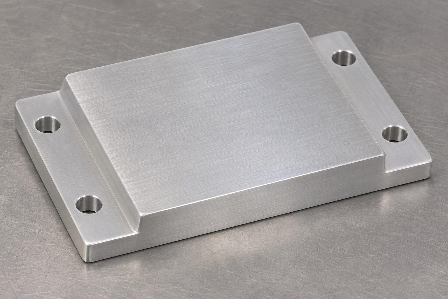
This representative machining example shows a bare 6061 aluminum spreader for the internal electronics of a portable ultrasound instrument. It is not an actual customer delivery and does not claim a measured temperature change, certification or device performance. The concept consists of a broad raised rectangular contact land, two lower mounting ledges and four plain through holes. No thermal pad, electronics or fasteners are included in the depicted part. The useful engineering exercise is to relate the raised land to the mounted stack and decide how those surfaces would be manufactured and checked.

Define the two contact interfaces
The land would face a specified interface material in the electronics assembly, and the plate would conduct heat toward an approved receiving structure. The enclosure designer would identify how that receiving structure contacts the spreader; the image alone does not define the complete heat path. The mounting ledges provide a mechanical interface and should not automatically be treated as an adequate thermal connection. Draw the stack and identify the contact and clearance zones on each side. An approved design would also name any areas that need protection from electrical contact or mechanical loading.
Use the mounting plane to set the gap
In the proposed drawing, step height is measured from the seating faces defined by the mount to the usable center land. The hole pattern permits assembly and is not assumed to determine the gap. The equipment team would supply the stack limits, interface material and allowed pressure or compression condition. A dimension on the plate alone cannot supply that information. Before releasing a drawing, compare tolerance limits for the mount, electronics and plate. If the contact area shifts toward a blended edge in one combination, revise the contact map rather than interpreting the radius as usable land.
Choose stock and process records
The scenario assumes a specified 6061 stock condition with lot identification and material documentation. Before machining, the shop would check whether the stock leaves enough allowance for both the mounting plane and the raised land. A change in stock form or treatment would require approval if it affects dimensions or the finish requirement. The photograph's bare metallic look does not determine alloy or temper. A real purchase order should identify the material evidence required, whether the part is supplied bare and which final surface conditions are acceptable after cleaning and packing.
Rough the steps while preserving support
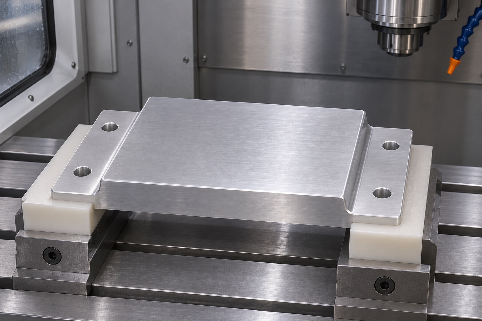
A candidate machining route faces the blank, establishes stable supports and roughs the two side ledges, leaving allowance on functional surfaces. Check after an intermediate release whether the blank has moved before using the final cut to establish the contact land. The sequence would be selected using actual stock, machine and trial evidence. Avoid concentrating clamp force over the thin ledges just to obtain a flat reading. The generated machining picture illustrates a supported setup; it is not a fixture drawing or a prescription for feeds, speeds, force or workholding hardware.
Finish the land and mounting features
A finishing setup would protect the mounting references and allow the cutter to reach the broad land without leaving a ridge in the usable area. The two ledges and four holes would be finished to the approved pattern with attention to exit burrs and tool access. Hole location is checked relative to the defined datums, not estimated from the image. Treat transition blends as controlled clearance features if they approach the contact area. Deburring should not roll material onto a seating face or shift the effective height of the land after final measurement.
Create a released-state inspection map
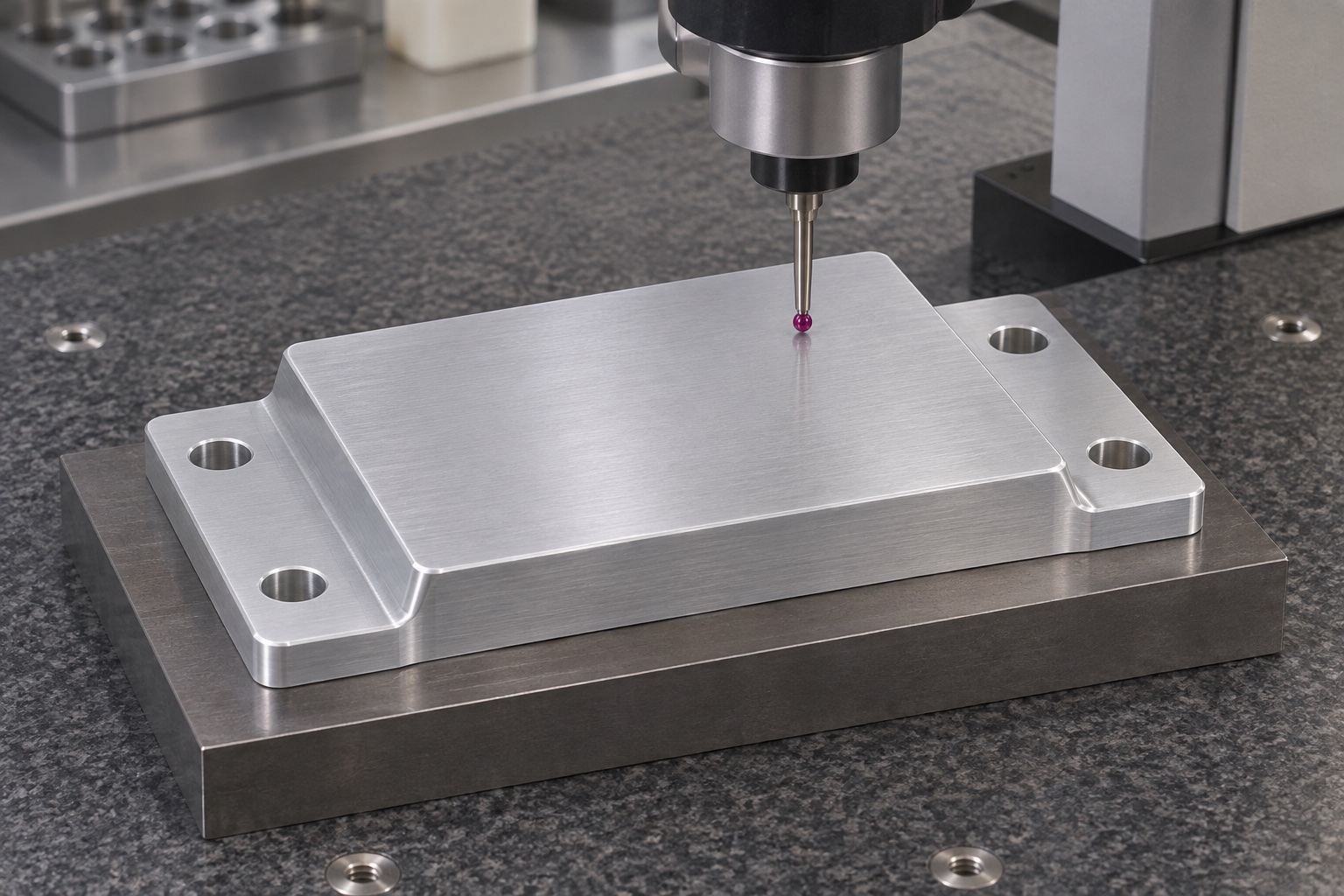
The proposed report would include the support condition, datum establishment and multiple land-height readings at specified stations. Include a form assessment over the actual usable area if the drawing requires it. Check the ledges independently and record the hole pattern, not just the plate envelope. A coordinate machine or appropriate height method can be chosen based on access and required uncertainty. No dimensions or measured outcomes are represented here. If a probe contacts the blend instead of the land, resolve the method before comparing its result with any drawing limit.
Check for burrs, dents and contamination
A useful visual plan distinguishes raised damage that could change contact from harmless appearance variation permitted by the drawing. Inspect the contact land, ledge seats, hole exits and step transitions under appropriate lighting. Loose chips must not remain at the edge of a hole or under a protective insert. Select a compatible cleaning process with the equipment owner and define the condition at packaging. Neither a shiny surface nor an illustration demonstrates a cleanliness classification. A failed surface should be reviewed before an operator uses abrasive blending or adhesive film to conceal the defect.
Use a build review to find interference
An engineering trial would install the spreader against a representative support, with a dummy board or approved assembly as appropriate. Check fastener entry, tool access and clearance to the electronics. Confirm the planned contact zone against the gap and compression requirements provided by the owner. A fit check may show a pinched edge, a rocking mount or a screw that obstructs access. It does not establish safe operating temperature or any other functional result. Record the build condition and resolve mechanical issues before moving to a controlled powered test.
Keep the thermal test outside the machining claim
For an actual instrument, the responsible team would define the heat input, environment, operating mode and temperature measurement locations. The contact material, assembly pressure and enclosure state should match the intended configuration. Changing the pad or plate geometry after that test can change the conditions and may require another review. This example reports no completed thermal test. It shows the manufacturing evidence that would be available to the designer: material, feature geometry, surface condition and a part that can be traced to an agreed drawing and process.
Specify transit protection and receipt checks
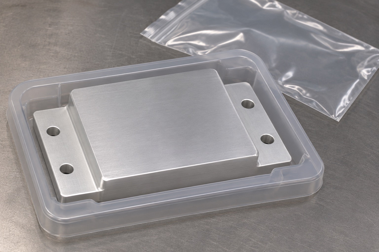
A fitted nonsterile protective pocket can support the plate at noncritical surfaces and separate the contact land from other components. Keep abrasive materials, tape and label adhesive away from the land and mounting faces. If the approved package uses film, describe how to remove it without residue. Label the lot and revision outside the functional surfaces. At receipt, check the pocket and part for impacts before inspecting the dimensional report. This packing concept is only an example of physical protection; it does not imply a certified cleanroom, sterile barrier or validated storage life.
Define deliverables for the real part
A real release would require the current drawing, approved material and finish, dimensional acceptance criteria, traceability and packaging instructions. The first article could include a feature map, list of measured stations and notes on the measurement state. Record assembly observations separately from formal acceptance and identify any unresolved requirements. The representative case does not include production volumes, turnaround times or performance guarantees. Its purpose is to show how to buy and inspect a stepped spreader with defined contacts, without extending the supplier's manufacturing evidence into a claim about the complete ultrasound system.
Manufacturer background reference: next.henkel-adhesives.com.
FAQ
Was this spreader manufactured for a named customer?
No. This is a representative machining example with illustrative imagery. It does not present an actual purchase order, completed delivery, test report, approved device design or thermal performance result.
What are the visible features in the concept?
A bare aluminum plate with one raised rectangular contact land, two lower mounting ledges and two plain clearance holes on each ledge. The assembly's pad, fasteners and electronics are outside the concept, and dimensions must come from the drawing.
What datum controls the land height?
Use the specified mounting seating plane, established with the approved supports or fixture condition. Measure to the usable land and avoid transition radii. A reading to the overall plate envelope or a convenient outside edge cannot substitute for that relationship.
How is part deformation addressed?
Review stock removal and workholding, consider an intermediate release, and measure the part under the defined acceptance condition. A reading from a part forced flat in the fixture does not by itself demonstrate released shape or installed fit.
Does the example state a measured temperature drop?
No. The example does not report any thermal test. The complete electronics assembly, interface material and enclosure must be evaluated by the equipment owner using defined power, environmental and measurement conditions.
Is the pictured packaging sterile?
No. The illustrated tray and bag represent protective separation. A real order should specify the agreed surface and contamination controls, while any sterile barrier or controlled cleanliness claim requires separate requirements and validation.

tanghangyun@oemach.com