
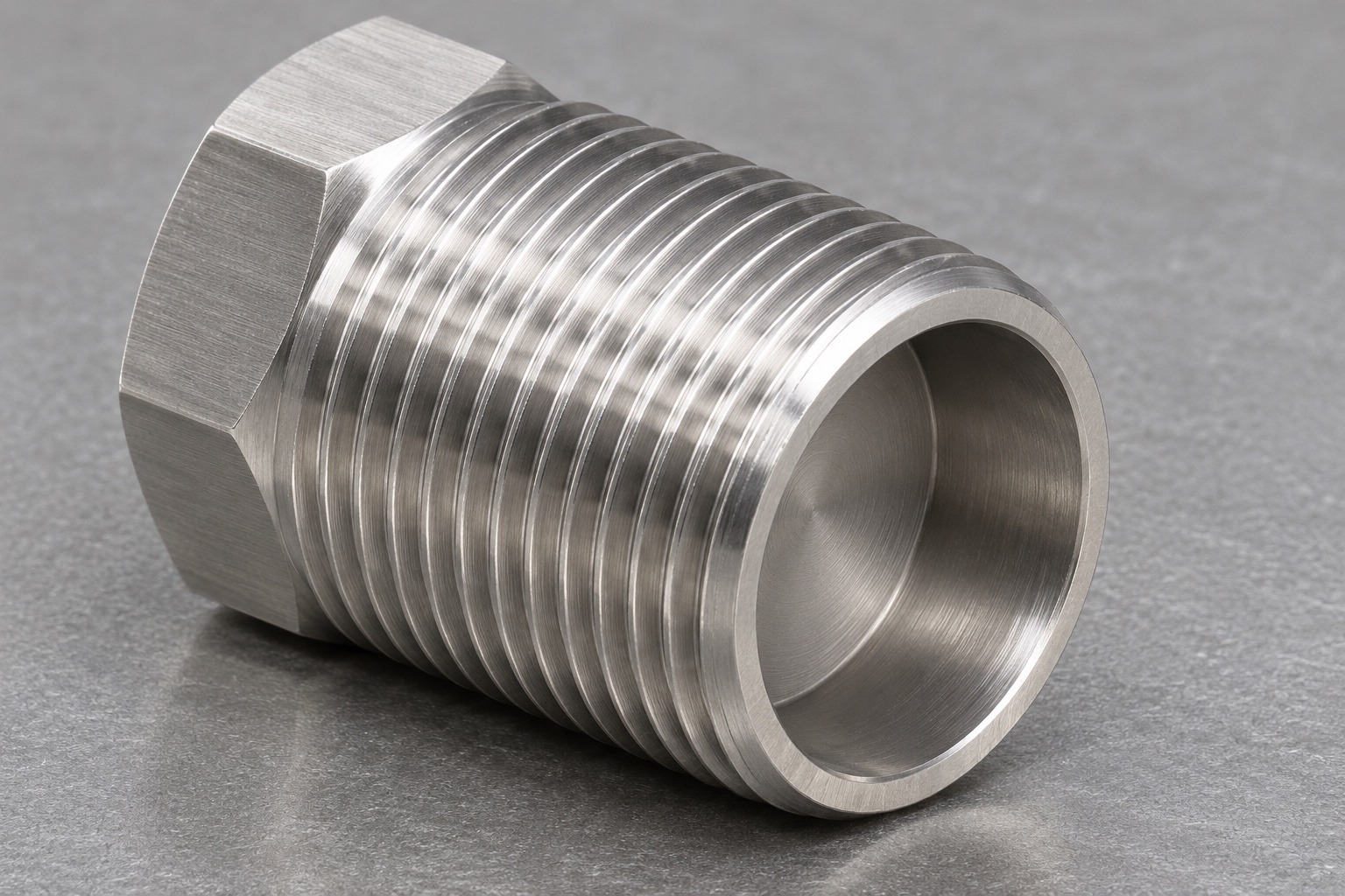
Define the representative example and its boundaries
This case describes a proposed CNC workflow for a 316L stainless steel housing body considered for an internal medical equipment mechanism. It is a representative example, not a delivered customer order or a completed spring-loaded device. The generated illustrations show an externally threaded short cylindrical body, a hexagonal closed rear head and one smooth blind axial cavity opening at the front. No spring, ball, moving pin, retaining cap or internal thread is included. A real project would require an approved body drawing and a separately defined assembly design before any functional performance could be evaluated.

Collect the missing assembly information first
The technical review would ask what locates the body in the equipment and how the eventual internal parts would be assembled and retained. A cavity and outside thread are not a complete retention design. The design owner would identify those interfaces instead of leaving a supplier to invent them from a commercial spring plunger's appearance. The example provides no spring force, stroke, operating load or contact condition. Any later change needed for retention would return to the controlled drawing rather than being added informally after machining the body had already begun.
Confirm material identity and requested records
The order review would identify the specified 316L condition, stock source and required material documentation. Those records would be kept separate from any requested surface treatment or cleanliness evidence. The example does not assert that passivation, sterilization or medical certification has taken place. If the real specification required a surface process, the technical review would identify its standard, responsibility and acceptance evidence before production. Stock selection would also allow suitable support during the proposed operation sequence, rather than assuming the outside thread or a thin cavity edge could serve as a convenient gripping surface.
Relate the external thread to the seating face
The released drawing would identify the external thread designation, usable engagement and the intended lead-in and runout regions. It would also distinguish a locating face from a wrenching face on the hexagonal head. The manufacturing plan would record which surfaces establish the important relationships during turning and any subsequent operation. No metric size, thread class or tightening torque is invented in this case. A real mating component or installation procedure would need its own identification so the acceptance review could address actual seating and access rather than only outside appearance.
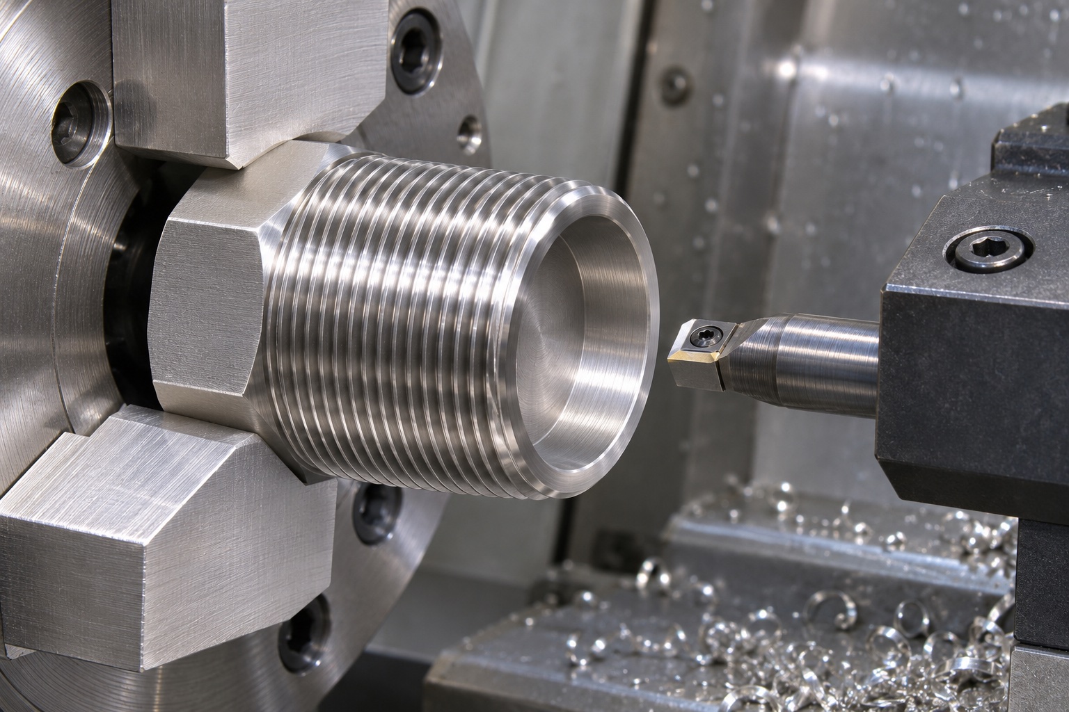
Plan the smooth blind cavity as a separate feature
The concept contains a smooth cylindrical cavity with a solid flat floor and no passage through the rear head. The drawing would define its diameter, depth reference, floor geometry and entrance condition. The process review would identify the appropriate tools and access for the final dimensions. Total outside length would not substitute for a direct cavity-depth requirement. If the designer permitted a different bottom shape, that permission would be documented explicitly. The generated image cannot supply a minimum wall thickness, an acceptable internal radius or any numerical cavity measurement for production.
Use workholding that protects finished interfaces
The proposed setup would review how to support the body while machining the outside thread and blind cavity. The rear hexagonal head may provide an accessible holding region, but its suitability would depend on the final geometry and approved surface condition. Finished threads would not be gripped in unprotected hard jaws merely because they were easy to reach. If more than one setup were required, the plan would identify the locating surfaces and verification needed at each change. The illustration communicates possible tool access; it is not a validated fixture drawing or a universal process instruction.
Control chips at the closed floor
The blind cavity would receive specific attention for chip removal and any retained process fluid. The route would define how the operator checks access and removes fragments without changing the cavity entrance or drilling through the floor. A visible clean rim would not establish that the deepest region was free from loose material. Tool choice and cutting conditions would be determined for the real component and machine. No cycle time, production yield or cleaning result is reported here. The point of the example is to keep an easily overlooked closed recess within the manufacturing and inspection review.
Inspect the external thread and cavity independently
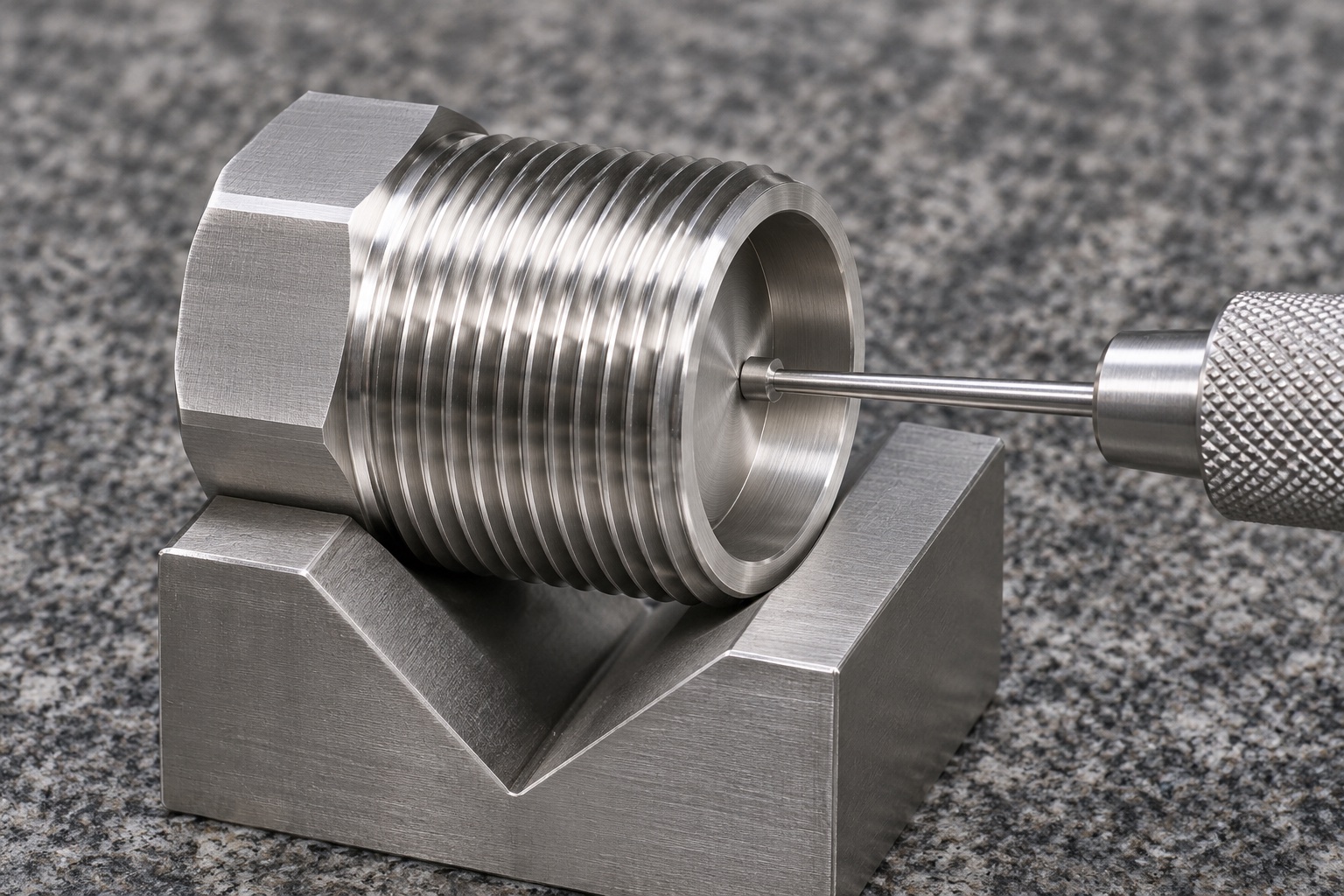
The acceptance plan would identify a method for the external thread and separate methods for bore geometry and depth where required. Gauges and measuring contacts would be selected for the actual drawing, not simply because a tool looked plausible in a photograph. A depth probe would reference the specified face and contact the intended floor region. The report would identify the component revision and measured feature. No numerical reading, gauge pass result or actual sample acceptance is claimed by this case, and the illustration does not establish the body's remaining material or overall conformity.
Review the relation between internal and external geometry
If the design required the cavity axis to relate to the external thread or another datum, the inspection plan would explain how that relationship was assessed. Checking the hexagonal head across flats would not automatically establish it. The support and reference scheme would be reviewed alongside the machining sequence so inspection remained achievable on the finished part. A limited installation observation could examine access and seating in identified mating hardware. It would not demonstrate a spring assembly's force, travel, retention or fatigue behavior, because those components and functions are outside the unassembled body concept.
Finish edges and clean without changing geometry
The final review would include the outside thread start and runout, cavity entrance, wrench-head edges and accessible internal floor. Burr removal would follow the approved edge requirements rather than uncontrolled polishing for appearance. The cleaning route would be compatible with the actual material, process residues and intended use. Any requested passivation would require its own process definition and records. This example reports neither a surface-treatment result nor a particle count, sterile condition or patient-contact approval. These requirements would need explicit evidence in a real medical manufacturing order, separate from the body being visibly bright.
Protect the thread and keep the cavity clear
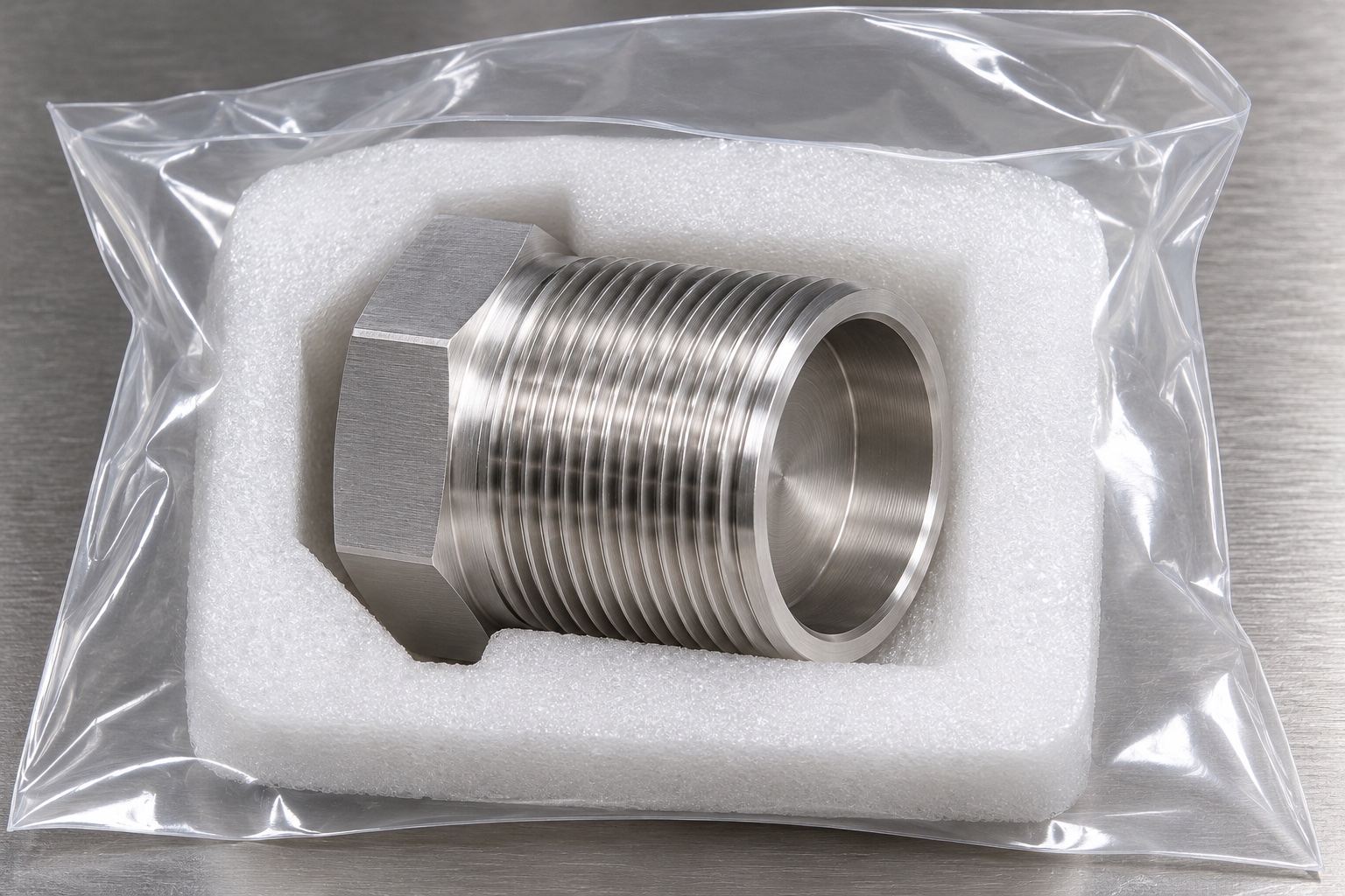
The proposed protective package would separate individual bodies so the male threads did not strike neighboring parts. A suitable pocket would support the main body, while the cavity would remain free of loose fibers, labels or unapproved foam plugs. Identification and traceability information would remain outside the functional surfaces. The clear bag and fitted foam in the illustration are not a validated sterile barrier or a transport test result. The real packaging specification would state the protections and documentation required for the order, including any separately qualified cleanliness or handling process if one were requested.
List the records needed to turn an example into a case
A genuine delivery report would require the released drawing, material identification, actual manufacturing records, measured inspection results, approved deviations and shipment evidence. This representative example does not claim any of those completed events. It describes a reviewable route for a particular threaded body with a blind cavity and closed rear head. To request a comparable quotation, provide the drawing and model revision, quantity, material condition, external thread, cavity requirements, reference scheme, finish, inspection deliverables and packaging needs. Include the separate assembly design wherever retention or spring-loaded function must be discussed.
Manufacturer background reference: www.carrlane.com.
FAQ
Was a functioning spring plunger manufactured for this case?
No. This is a representative housing-body workflow with generated illustrations. No actual customer delivery, manufactured sample, assembly trial or spring-force result is reported. The moving element, spring and retention design are not included in the concept.
Which end of the housing is open?
The front end opens into a smooth axial blind cavity. The opposite end has a closed hexagonal rear head. The cavity does not pass through that head, and its floor and depth must be defined in the real drawing.
Does the example include an internal thread or retaining cap?
No. The thread is on the outside cylindrical wall only. No cap, internal thread or retention detail is illustrated as a completed design. Those features would require explicit assembly information and approval before being added to the controlled component.
What does the inspection illustration demonstrate?
It illustrates possible access to the cavity for a depth-related observation. It contains no readable measured value or acceptance result. A real inspection plan must separately address the required thread, bore, depth and geometric relationships using suitable controlled methods.
Is the body certified sterile or passivated?
No such condition is claimed. Material grade, surface treatment, cleanliness and sterile delivery are separate requirements. Any requested treatment or qualification needs its own specification and evidence; an alloy name or protective bag cannot establish those results.
What documents should accompany an inquiry?
Provide the released body drawing, model, quantity, 316L condition, external thread designation, blind-cavity dimensions, references, finish and required inspection records. Include cleaning, packaging and any separate assembly design needed to review the eventual moving and retaining components.

tanghangyun@oemach.com