
A representative component rather than a customer delivery
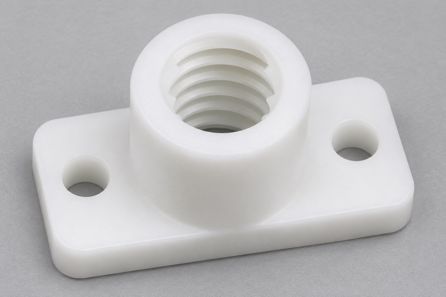
This case is a proposed manufacturing workflow for a lead screw nut considered as an internal mechanical component of a medical analyzer. It is not a report of a delivered customer part, a validated device or a measured motion system. The generated images show one white POM-C body: a rectangular flange, a central cylindrical boss, one internal axial trapezoidal through thread and two plain mounting holes. No screw, ball circuit, split mechanism or preload spring is supplied as part of the concept. A real project would begin with approved design documents and identified mating components.

Resolve the screw identity before quoting the nut
The initial review would request the exact thread designation and the mating screw information. Nominal diameter, pitch, lead, number of starts and handedness would be checked rather than guessed from an image. The order would identify how thread conformity and any required fit observation were to be accepted. If the screw drawing were unavailable, the technical review would flag that information gap instead of inventing a generic compatible profile. This example provides no numerical thread size or acceptance result because there is no released physical design or manufactured sample behind the illustration.
Confirm the polymer stock requirement
The proposed material review would identify the actual POM-C grade, color, stock form and documentation requested for the order. White appearance would not be treated as proof of a particular grade or medical classification. The design owner would separately review the intended environment, cleaning agents and contact requirements. The machining plan would consider stock history and material removal before defining the operation sequence. No thermal treatment, chemical compatibility result, sterilization cycle or biocompatibility certificate is claimed in this representative case. Any required evidence would have to be specified and obtained for the actual project.
Establish the flange and boss reference scheme
The controlled drawing would identify the mounting face and describe its relationship to the thread axis and mounting-hole pattern. The setup review would use these functional references rather than relying on an arbitrary outside corner because it was easy to touch with a probe. The proposed flange support would leave access to the central bore and the two plain holes. If a second setup were required, the process plan would identify how the original references were preserved. The component would be inspected in its released condition rather than only while held under machining fixture pressure.
Machine the outside form without inventing preload features
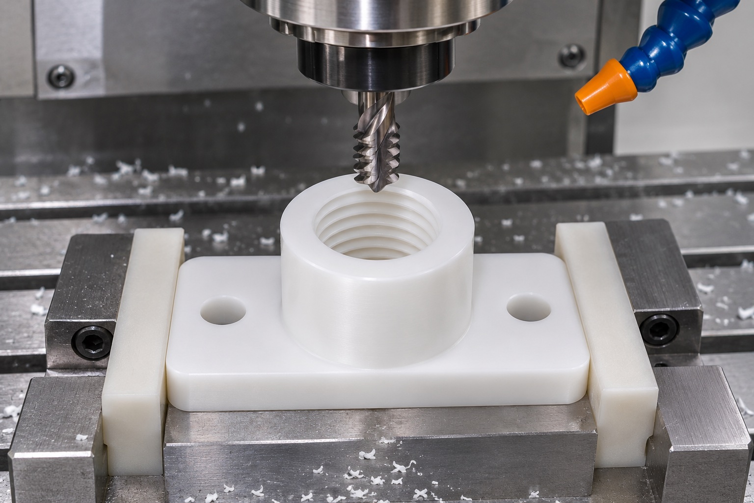
The proposed outside form contains a flat rectangular flange and a centered cylindrical boss with an annular top face. Its corners may be eased only as required by the final drawing. The manufacturing instructions would exclude any unapproved split, spring seat or adjustable section, because those would create a different mechanism from the one-piece concept. Workholding would support the flange while leaving the boss and thread bore accessible. Tooling and cutting conditions would be selected for the actual material and machine, not presented as universal parameters or as evidence of an achieved dimensional capability.
Produce the through thread with a defined entry and exit
The thread operation would be planned from the approved profile, engagement length and access conditions. The review would address the tool path at both bore entrances and the removal of chips from the thread roots. A through thread would not be assumed clean merely because light could pass through it. Any process fluid would need a compatible removal route. The illustration shows a possible machining context but does not prescribe the exact cutting method for every part size. No thread class, measured flank dimension or production acceptance percentage is reported in this example.
Keep the two mounting holes plain and controlled
The two holes in the rectangular flange would remain unthreaded unless the approved drawing explicitly required a different geometry. Their positions would be related to the identified mounting references and central thread axis. Deburring would preserve the required edge condition without creating unintended countersinks. The review would also consider fastener-head access and nearby assembly clearances using the real mating model. Those checks are distinct from the simple statement that the hole spacing meets a dimension. No bolt size, tightening torque or approved mounting arrangement can be inferred from the generated component image.
Agree the thread and geometry inspection plan
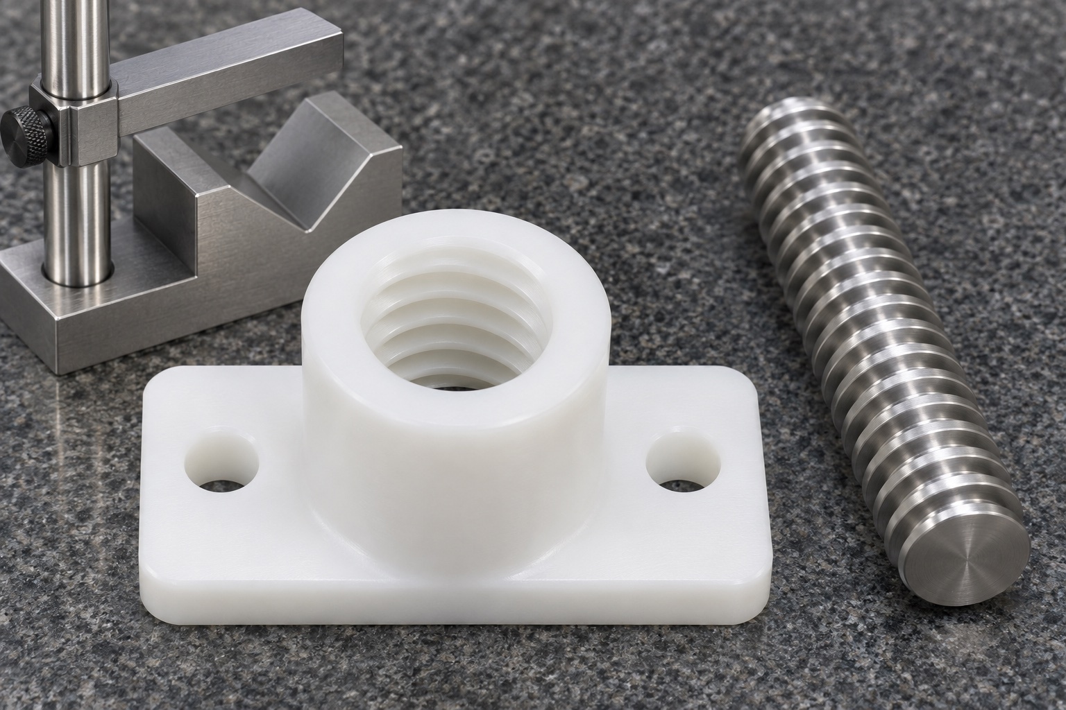
The inspection plan would identify the methods used for the internal thread, flange dimensions and relationship between the mounting face and thread axis. Any checking screw or gauge would be identified and maintained in an agreed condition. A hand engagement could be recorded as a limited assembly observation, but it would not silently become complete thread acceptance. Measurements would be linked to feature identifiers and the drawing revision. The inspection picture contains no readable result, no approved gauge outcome and no claim that a physical component has passed the proposed checks.
Observe installation without claiming motion accuracy
An optional nonclinical development observation could examine seating and alignment using the actual screw, guides and mounting hardware. The procedure would identify the fastening sequence and the conditions under which movement was observed. Unexpected resistance would prompt an interface review rather than forceful engagement or undocumented modification of the nut. A favorable observation would not establish positioning accuracy, backlash, repeatability, load capacity or service life. These outcomes belong to evaluation of the complete mechanism. Any approved change would return to the controlled drawings and inspection requirements before a revised component was treated as production-ready.
Remove residues from functional recesses
The proposed cleaning review would focus on the internal thread roots, bore entrances and plain mounting-hole edges. The chosen process would need to be compatible with the specified polymer and intended equipment use. After cleaning, accessible features would be checked for retained chips or other loose material. The component would not receive unapproved abrasive treatment that changed thread engagement or rounded a functional face. This representative workflow reports no particle-count result, validated cleaning qualification or sterile condition. Those requirements would require separate specifications, process evidence and acceptance records in a real medical manufacturing project.
Separate protected parts during shipment
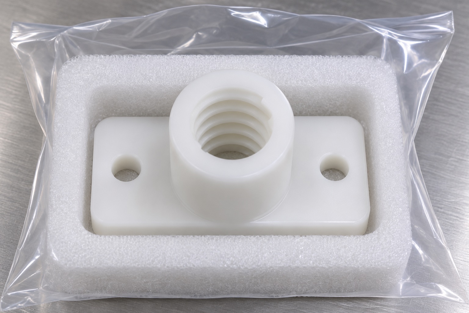
A protective arrangement would separate the finished nut bodies and avoid pressure on the threaded boss or flange edges. Clean bags or suitable separators would be specified according to the actual handling needs, with identification outside the functional thread. Packaging materials would be reviewed for the risk of loose fragments entering the bore. The open bag and foam illustrated here show an idea for protection, not a validated sterile barrier or transport qualification. A real shipment record would identify the revision, quantity, material traceability and any required handling instructions agreed for the order.
State the evidence needed for a genuine delivery case
A documented delivery case would include the released design, material records, manufacturing history, actual inspection results, approved deviations and shipment evidence. None of those events is asserted by this illustrative example. Its value is the explicit relationship between thread identity, flange alignment, workholding and acceptance planning for a particular component concept. An inquiry should include the complete screw interface, model and drawing revision, quantity, material grade, documentation and packaging requirements. This keeps a manufacturing proposal grounded in actual interfaces without converting a white plastic nut or a generated photo into a motion-performance claim.
Manufacturer background reference: www.thomsonlinear.com.
FAQ
Is this a completed medical analyzer order?
No. It is a representative machining example with generated images. There is no claimed customer, delivered quantity, measured sample or validated analyzer result. A real order would need its own released documents, production records and acceptance evidence.
What geometry is shown in the concept?
A one-piece white POM-C nut with a rectangular flange, central cylindrical boss, one internal axial trapezoidal through thread and two plain flange holes. No ball circuit, split body, preload spring or mating screw is included in the component concept.
Can an existing screw be used as the inspection master?
Only under an explicitly agreed method that identifies the screw and its condition. An uncontrolled development screw should not become a production acceptance standard. Thread geometry checks and limited assembly observations should be described and recorded separately.
Does the example demonstrate low backlash?
No. No backlash or positioning measurement is reported, and the body has no designed preload mechanism in this illustration. Motion characteristics require the actual screw, nut, installation and complete mechanism to be evaluated under defined conditions.
Are the two flange holes threaded?
No. They are plain mounting through holes in this concept. Their size, position and edge condition would be defined by the real drawing. A threaded mounting pattern or other locating arrangement would be a separately approved design change.
What should be supplied for a similar quotation?
Provide the complete thread designation, mating screw identification, drawing and model revision, quantity, polymer grade, mounting-face references and inspection needs. Include cleaning and packaging expectations and any separately specified nonclinical assembly observations required for the project.

tanghangyun@oemach.com