
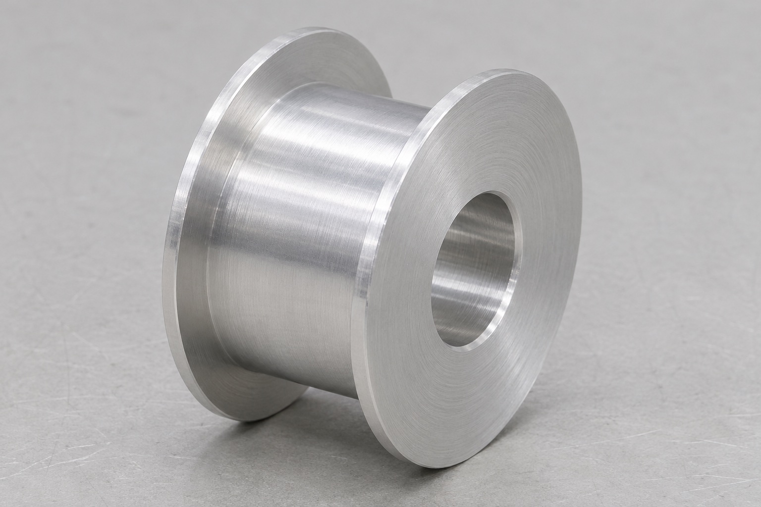
Representative example, not a delivered customer part
This case describes a proposed machining workflow for a smooth flanged idler pulley intended for discussion within a medical analyzer mechanism. It is a representative example, not a report of a customer order, production delivery or successful equipment trial. The images are generated illustrations. The concept is a single 6061 aluminum body with two equal circular flanges, a smooth smaller-diameter barrel and one concentric through bore. No bearing, shaft, belt or fastener is included. A real project would require an approved drawing, identified mating components and independently defined acceptance requirements.

Translate the mechanism description into drawing inputs
The first review would ask how the pulley is supported and which belt surface meets the barrel. The requested information would include the mounting axis, axial locating face, belt width and surrounding assembly clearances. These inputs would be recorded before a manufacturing route was selected. The example does not invent a belt size, rotational speed, load or flange dimension. If the equipment drawing and component model disagreed, the discrepancy would return to the design owner instead of being resolved by assuming that the generated image represented a release-ready design.
Confirm material and finishing responsibility
The inquiry would identify the specified 6061 condition and the material documentation required for the intended lot. Stock selection would allow suitable support during turning without treating the thin flanges as convenient clamping surfaces. Any coating or finishing proposal would be reviewed for its effect on the bore, barrel and usable flange spacing. The order would state whether acceptance dimensions apply to the finished condition. No anodizing thickness, corrosion result, medical certification or material test report is claimed here. Such evidence would need to come from the actual agreed supply and processing records.
Prepare a bore-centered manufacturing plan
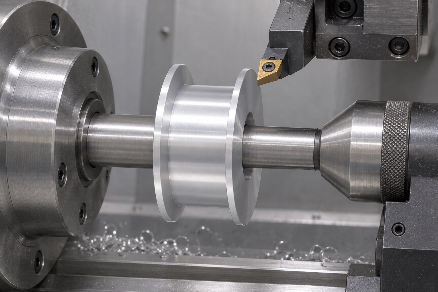
The proposed route would review whether the bore, one locating face and the barrel could be related in a controlled setup sequence. The manufacturing engineer would select the actual workholding method from the final drawing, stock size and machine access. A plain mandrel shown in an illustration only explains a possible reference concept; it is not a fixture specification. If reversing the component were necessary, the plan would identify the locating surface, seating check and remaining allowance. The thin flange edges would receive deliberate protection throughout handling and setup changes.
Turn the barrel without adding a tooth profile
The concept calls for a straight smooth cylindrical barrel between two flanges. The operation plan would therefore exclude timing teeth, decorative grooves and unapproved crowns. The tool path would address access near both inner flange faces while preserving their specified transitions. Cutting conditions and tool selection would be established for the real stock and machine rather than copied from an illustrative case. The operator would have clear feature identification so a finishing pass could not silently change the usable belt-contact width. The actual surface requirement would remain the approved drawing requirement.
Preserve flange clearance through finishing
Before release to production, the inspection plan would distinguish the total component width from the clear inner flange spacing. Chamfers and radii would be reviewed for their effect on the usable belt space. Deburring instructions would prevent the flange edges from becoming thinner or more rounded than intended. If a finishing supplier were involved, masking and dimensional responsibility would be documented for the bore and contact barrel. This example reports no finished dimensions or coating results. It illustrates why the assembly clearance must remain visible in both the manufacturing instructions and the final acceptance plan.
Check the bore using an agreed method
The bore inspection would identify measurement positions and the instruments appropriate to the drawing requirements. A bore size check and an assessment of its relationship to other features would be treated as separate tasks where the drawing requires both. The report would identify the part revision and measured feature, avoiding a generic statement that the pulley was simply checked. Any reference mandrel would be reviewed for fit and condition before use. No bore tolerance, measured value or acceptance percentage is supplied because no physical sample has been manufactured or inspected for this example.
Define barrel and flange runout observations
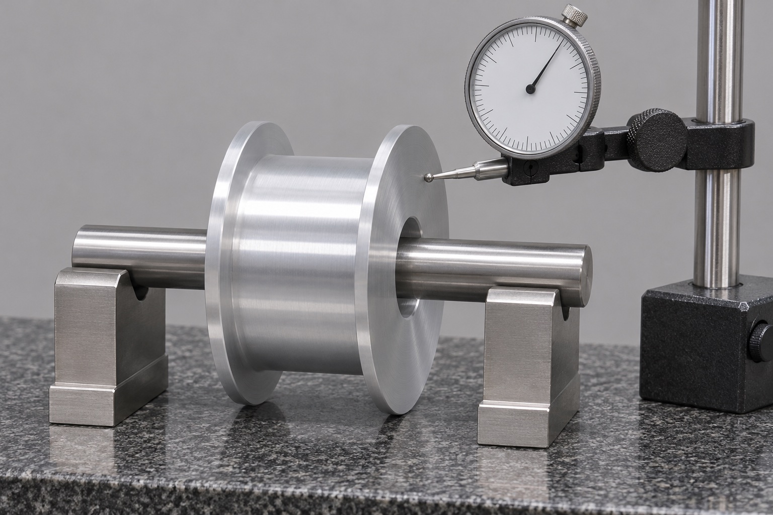
If required by the final drawing, the proposed inspection would support the pulley from the approved reference and distinguish radial observation of the barrel from axial observation of a flange face. The method would record the contact location, seating condition and applicable limits. A clean support surface and controlled rotation would be part of the setup review. The indicator image does not show a readable measurement. Even a conforming dimensional report would not by itself establish the belt drive's tracking behavior, service life, dynamic balance or accuracy within the complete medical analyzer.
Review burrs, chips and surface protection
The final visual review would include bore entrances, inner flange corners, outside flange edges and the smooth contact barrel. Loose chips would be removed using a compatible documented process, followed by a check for retained fragments. Functional edges would not receive uncontrolled polishing simply to make the component look bright. Any cosmetic condition would be agreed separately from dimensions where appropriate. This example does not claim a validated cleaning process or particle limit. The intended use remains a mechanical equipment component, with no assertion of sterile delivery or direct patient-contact suitability.
Limit an optional development assembly check
An optional nonclinical observation could examine installation clearance and free access with identified mating hardware. The test record would name the actual shaft or bearing arrangement, spacers and belt configuration used. A favorable hand rotation would not become a claim about load capacity, speed, belt wear or analyzer safety. If the assembly bound or a flange contacted another component, the team would investigate the reference geometry before altering the part. Any approved change would return to the drawing and inspection plan, and modified development samples would remain distinguishable from a released production configuration.
Package the component without implying sterility
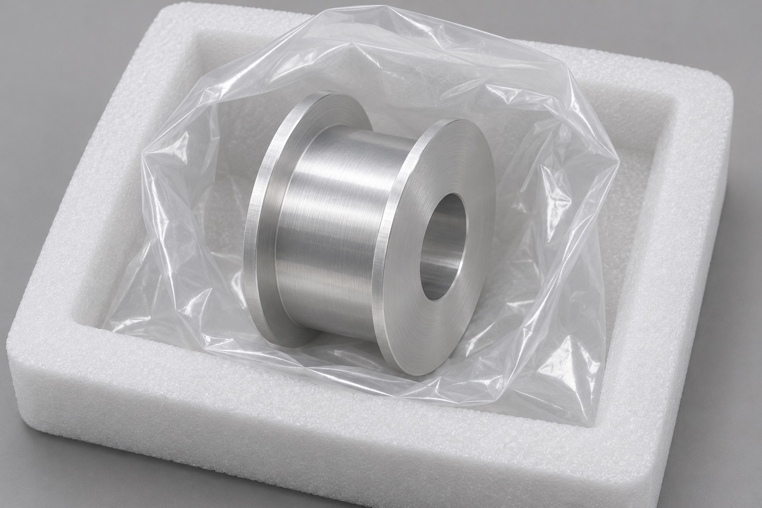
The proposed protective arrangement would separate pulleys so their flange edges could not strike each other. A suitable pocket would support the main body and avoid loading the thin edges. The bore would remain free from loose packaging debris, and identification would stay outside the functional surfaces. The packaging description would state whether bags, separators or other protections were required for the actual order. The illustrative open bag and foam are not evidence of a sterile barrier, cleanroom classification or validated transport performance. Those requirements would need their own approved specifications and supporting records.
Define what a real case record would contain
A genuine delivery case would require evidence such as the released drawing, material identification, manufacturing traveler, inspection results, approved deviations and shipment records. This representative example provides none of those as completed events. Its purpose is to show a reviewable sequence from interface definition to protected handling for one particular pulley geometry. A quotation request should include the model, quantity, bore requirements, contact profile, flange clearances, finish and documentation needs. The manufacturing proposal can then address real acceptance conditions without borrowing performance claims from a belt supplier or treating an illustration as proof.
Manufacturer background reference: www.gates.com.
FAQ
Was this pulley delivered to a medical customer?
No. It is a representative machining example with generated illustrations. No customer, order quantity, shipment, measured sample or validated performance result is asserted. A real project would need its own controlled design and documented production evidence.
What is included in the illustrated component?
Only the single machined aluminum body is included: two flanges, a smooth barrel and a concentric through bore. There is no bearing, belt, shaft or fastener. The required mating components must be identified separately for a real assembly.
Why is flange spacing reviewed separately?
The clear span between inner flange faces governs a different interface from the overall outside width. Edge transitions and finishing may also affect usable clearance. Both the drawing and the inspection plan should identify the intended surfaces and acceptance conditions.
Are numerical tolerances available from this example?
No numerical tolerances or inspection readings are reported. They must come from the approved drawing and actual measurement records. A generic runout illustration cannot define a bore fit, flange limit or acceptable drive performance.
Does protective packaging establish medical compliance?
No. Individual separation and bore protection describe handling measures only. They do not establish sterility, a particle classification, material biocompatibility or approval of the complete device. Any such requirements need separate specifications and evidence.
What is needed to quote a comparable part?
Supply the model and drawing revision, quantity, specified material condition, bore interface, barrel profile, flange clearance, finish and required documentation. Identify the belt contact and assembly arrangement so manufacturing review can focus on the actual interfaces.

tanghangyun@oemach.com