
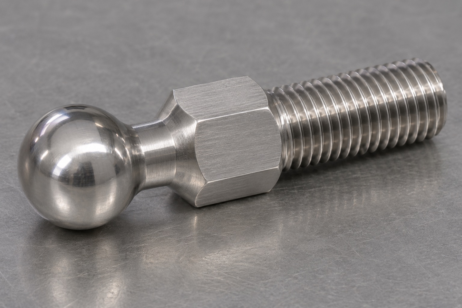
Scope of the representative manufacturing example
This representative example proposes a one-piece 316L adjustment stud for an internal medical equipment alignment mechanism. It has an integral spherical end, a short neck, a hexagonal wrench section and a male thread at the opposite end. It is not a report of a customer delivery or an actually measured production sample. The ball does not rotate independently, and the component is not a complete ball joint, locking assembly, implant or fluid connector. The proposed route describes manufacturing decisions without claiming achieved tolerances, load capacity, adjustment stability, fatigue life, wear performance, certification or sterile delivery.

Review the mating contact and adjustment concept
The proposed first review would obtain the controlled model, drawing, mating surface and required tool-access envelope. The equipment designer would identify the intended spherical contact region and useful adjustment range. Any locking or retaining components would be separately defined. The review would confirm that turning the threaded stud also turns its integral tip, unless the surrounding mechanism provides another arrangement. Open questions about sliding, angular clearance or contact damage would not be resolved by an attractive product image. The manufacturing release would follow an approved mechanical definition rather than an assumed commercial ball-joint configuration.
Maintain material identity through the route
A real purchase order would identify the required 316L specification, stock form and documentation. The proposed traveler would keep the blank identity associated with the part through turning, milling, finishing and inspection. A similar-looking stainless bar would not be substituted without approval. Any requirement for passivation or another surface process would be recorded along with the acceptance state. This example does not invent a certificate or claim that the material alone qualifies the component for a medical system. Application-specific cleaning exposure and biological or regulatory questions would remain within the responsible design and validation review.
Establish the axis and spherical-end definition
The programming review would identify how the approved thread-axis reference relates to the integral spherical tip. It would define the usable spherical surface and the transition into the neck, including any clearance needed by the mate. The turning proposal would avoid leaving a temporary grip or center mark in a specified working region. No actual radius, form tolerance or achieved concentricity is asserted here. Those values require the real drawing and measurement plan. A perspective silhouette would not replace a controlled section or the agreed reference system used by the programmer and inspector.
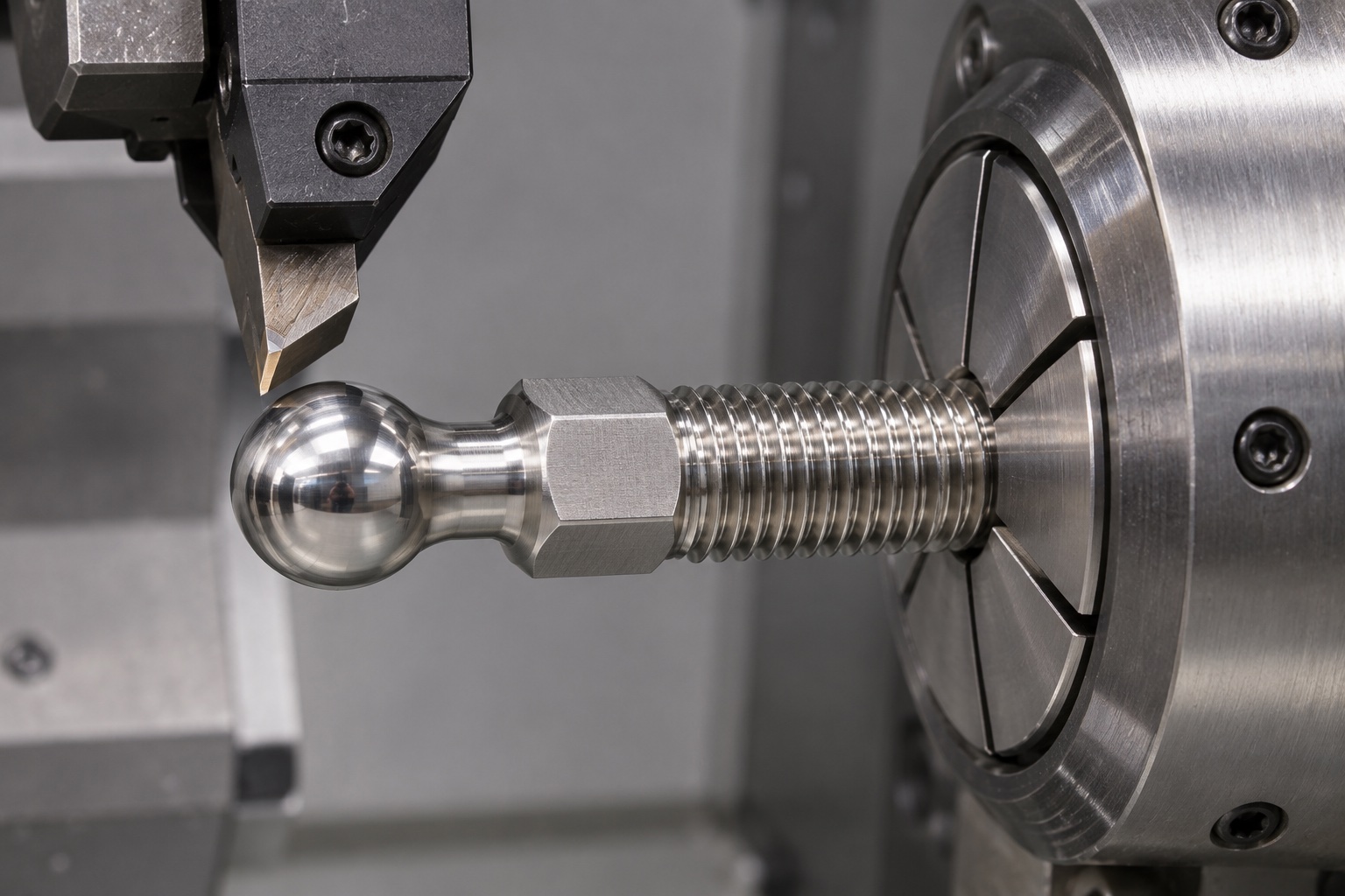
Produce the thread to its complete specification
The proposed threading operation would follow the released system, pitch, hand, fit and useful length. Entry and runout details would be checked against the mating component and the adjustment concept. The supplier would not treat every visible thread crest as available engagement or add an unspecified relief that removes a required bearing section. Process selection would depend on the actual geometry and equipment. No universal feed, cutting speed or assembly torque is supplied. The inspection plan would identify the appropriate thread checks without claiming that a passing gauge alone establishes retention or load capacity for the assembled mechanism.
Machine the wrench section without damaging the tip
The hexagonal section would be related to the same released geometry through the necessary setup change. The proposal would address across-flats size, usable tool-contact length and transitions. Workholding would avoid marking the finished sphere or loading a delicate neck in an uncontrolled way. The surrounding assembly would be reviewed for wrench access through the required adjustment range. If tool clearance was inadequate, the issue would return to engineering rather than being hidden by shortening the hex section at the machine. No locknut or separate tool would be assumed to be included with the illustrative stud.
Control transitions and the final surface condition
The neck, spherical transition, thread entry and wrench edges would be finished according to the approved requirements. Deburring would remove attached material without altering the defined contact envelope. Polishing, if ordered, would have a controlled scope and would not be used as an undocumented fitting operation. Any later passivation or other treatment would be reviewed for its effect on acceptance and handling. A bright surface would not be presented as a measured roughness result or proof of cleanliness. Changes to a contact region would require inspection rather than an assumption that a smoother-looking part is necessarily improved.
Inspect the tip, thread and their relationship
The proposed inspection plan would separately address the spherical profile, permitted contact extent, neck, wrench section and thread characteristics. It would also include any drawing requirement relating the tip to the approved axis. The method and sampling would be chosen for actual access and required uncertainty. A caliper diameter and a passing ring gauge would not automatically document the complete interface. Since no component has been measured for this representative example, there are no numerical results to report. A real inspection record would need identified instruments, actual values and acceptance decisions tied to the controlled drawing revision.
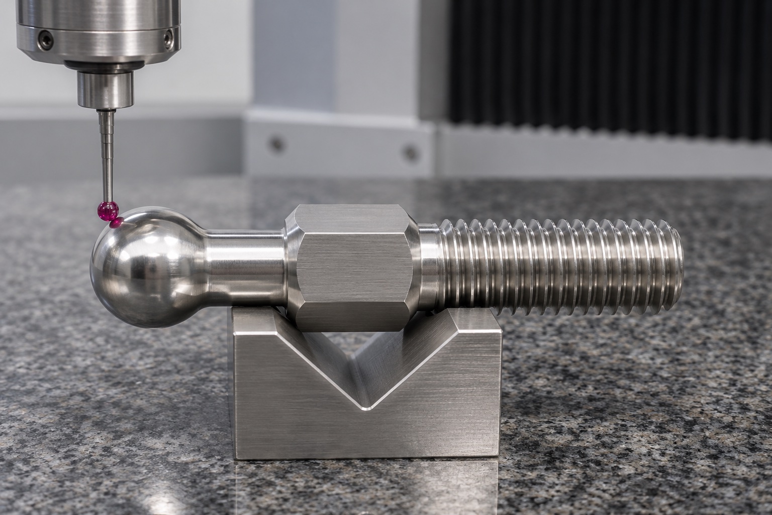
Retain a clear nonconformance and rework route
If an actual inspection found an unacceptable characteristic, the proposed process would identify the affected component and hold it for a documented decision. An operator would not grind the spherical tip or chase the thread merely to obtain a favorable assembly demonstration. Rework would require authorization and inspection of affected relationships. If the drawing itself needed revision, the change would be reflected in the model, program and inspection instructions. This distinction helps prevent a development adjustment from becoming an unnoticed production change. The example describes a control approach and does not claim any historical yield or defect reduction.
Limit an optional adjustment observation
An agreed observation could record installation, tool access, contact and movement over a specified adjustment range using identified mating parts. It would document the procedure and any separate retention components without inventing an approved tightening torque. Successful hand adjustment would not establish force capacity, fatigue resistance, wear life or long-term locking stability. Those outcomes require an appropriate evaluation of the real mechanism. Unexpected contact would lead to a review of the sphere, mate and references before either was altered. Trial components would remain distinguishable from released production and would not independently qualify medical equipment for service.
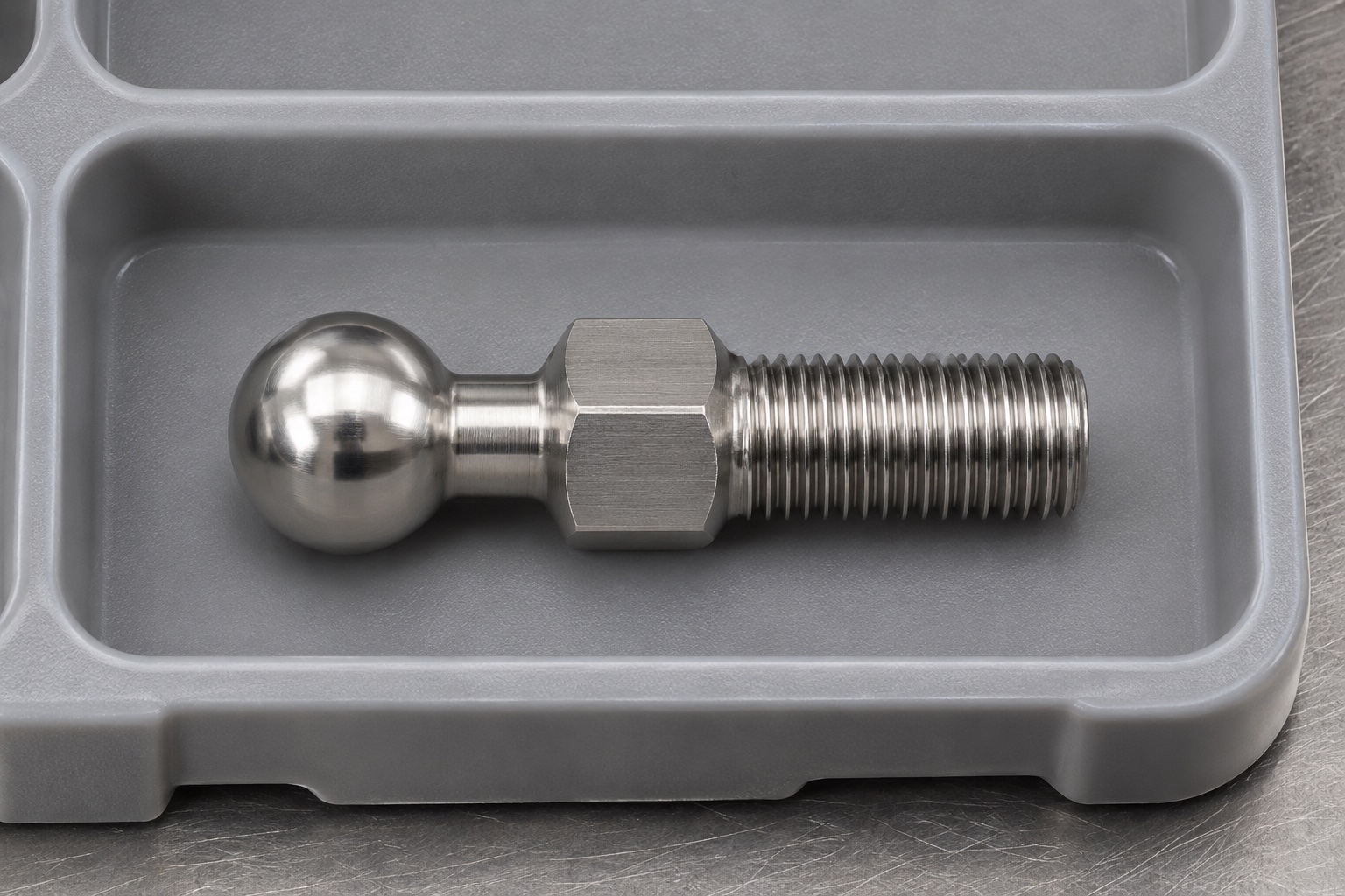
Protect the two critical ends during shipment
The proposed package would individually separate studs and prevent impacts on the spherical contacts and external threads. A tray, sleeve or other protective arrangement would be selected for the approved finish and any material restrictions. Identification would preserve the part number, revision and inspection status through dispatch. Packaging would not imply sterile delivery or validated cleanroom handling. If final cleaning occurred at the purchaser, the agreed handover condition would be stated. The illustration is a packaging concept only and should not be interpreted as evidence of a completed lot, a customer shipment or a verified medical-device supply chain.
Preserve the release basis for a repeat order
The repeat-order package would retain the exact spherical geometry, neck transition, thread definition, wrench-access requirements, material condition and inspection scope. A changed mating surface or locking arrangement would trigger review even if the stud's overall length remained the same. The purpose of this example is to support a precise supplier discussion about a custom adjustment component. It does not supply a universal ball stud or replace the equipment team's assessment of the complete mechanism. No customer identity or measured performance is invented, and real acceptance would depend on the actual released requirements and evidence for that project.
Manufacturer background reference: www.elesa-ganter.com.
FAQ
Does the example document a real production delivery?
No. It is a representative CNC manufacturing proposal with no claimed customer order, quantity, delivery date or measured result. Its purpose is to explain the information and controls a real project would need before manufacturing, inspection and acceptance.
Is the spherical tip free to rotate independently?
No. It is integral with the one-piece stud and rotates with the threaded body. A separate rotating ball or complete joint would be a different assembly with different manufacturing and inspection requirements. Such a construction is not implied by this example.
Are a locking nut and tightening torque specified?
No. Separate locking components and an approved assembly procedure belong to the actual equipment design. This example does not invent a torque or assume that a threaded connection alone provides a qualified adjustment-retention function for the complete mechanism.
What would need to appear on the inspection report?
The report would identify the drawing revision, applicable spherical and thread characteristics, reference relationships, actual instruments and results. The precise contents depend on the released requirements. A generic statement that the stud passed or looked correct would not replace those records.
Can a thread-fit demonstration establish load capacity?
No. A mating nut or gauge can address only limited interface questions within its defined scope. Contact geometry, material condition, engagement, loading and the full mechanism require an appropriate engineering assessment before any capacity or service-performance result could be claimed.
What should accompany a request for quotation?
Provide the controlled model and drawing, mating contact definition, complete thread specification, tool-access requirements, material and finishing scope, quantity, inspection requirements and protective packaging condition. Identify unresolved assembly and application questions before asking the supplier to manufacture the component.

tanghangyun@oemach.com