
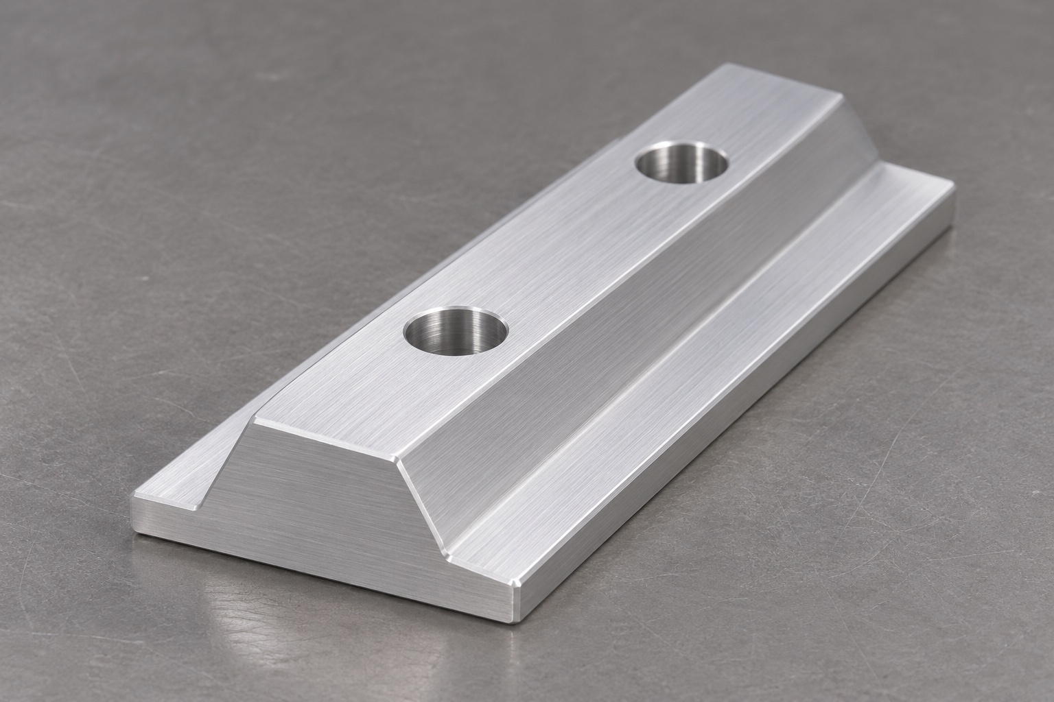
Scope of the representative example
This representative machining example proposes a 6061 aluminum locating rail for a removable internal medical analyzer module. It is not a report of a customer order, a manufactured sample or verified assembly results. The concept has a flat rectangular base, a raised ridge narrowing toward the top and two plain vertical holes. It contains no undercut or installed fastener. The example describes how a supplier and equipment designer could organize a manufacturing review. It does not claim achieved tolerances, positioning repeatability, retention capacity, service life, sterile delivery or certification of a medical system.

Review the mating arrangement before releasing the blank
The proposed first step would collect the controlled drawing, model and mating module definition. The review would identify where the module contacts the rail, how it is retained and which direction is used for removal. The ridge would not be treated as a captured slide. Screw access, insertion clearance and any stop feature would be checked in the assembly concept. Open questions would be recorded rather than answered by an operator on the machine. If a separate clamp were required, its relationship to the rail would be approved before a manufacturing plan was released.
Maintain the material and revision identity
A real order would specify the required 6061 grade, temper, stock form and traceability documents. The proposed route would preserve that identity through blank preparation, machining and any external treatment. Similar-looking aluminum offcuts would not be substituted because they fit the fixture. The material specification would remain separate from the application assessment of corrosion, cleaning exposure or biological suitability. At each handover, the traveler would identify the drawing revision and the ordered finish. This example describes documentation controls only and does not invent a material certificate or a qualified supplier approval.
Establish the base as an agreed machining reference
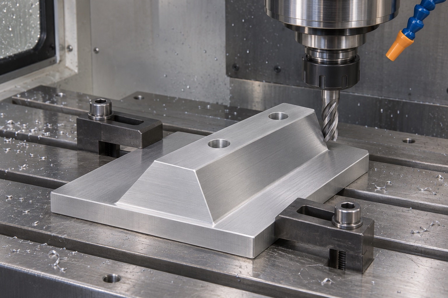
Blank preparation would provide sufficient allowance for the defined base and raised section. The fixture proposal would support the part without obscuring the required cutter approach. The base plane would be established and carried forward as agreed in the drawing and process review. Support and clamping would be selected for the actual dimensions rather than copied from an illustration. The inspection plan would state whether the rail is evaluated free from the machining fixture or in another explicitly specified condition. A temporary clamped shape would not be accepted as evidence of the delivered geometry.
Generate the raised trapezoidal ridge
The proposed milling sequence would establish the ridge height, top width and two sloping faces relative to the approved base. The programmer would confirm the angle convention and tool accessibility before selecting the final path. No particular spindle speed, feed or number of passes is claimed here; these require the real material, geometry and equipment. The narrowing profile would be preserved rather than replaced by a standard dovetail form. If the mating design required a different section, that would trigger a document change rather than an unrecorded adjustment to the machine program.
Relate the mounting holes to the working profile
The two plain through holes would be produced using the approved longitudinal and transverse references. Their relationship to the functional ridge would be maintained across any necessary setup changes. The review would identify how screw heads bear on the assembly and whether separate parts provide the seats. No countersink, counterbore or thread would be added to the illustrated rail without authorization. Tool access would be considered at the correct assembly stage. Any conflict between a hole, a working face and the required remaining section would be resolved before removing material from the blank.
Preserve transition and clearance details
The ridge-to-base junction would follow an approved radius or relief detail. The supplier would not promise a perfectly sharp internal transition that the selected manufacturing route cannot produce. Contact zones would be distinguished from noncontact clearance areas. If the mating module interfered with a permitted cutter radius, the issue would return to engineering rather than being hidden by local filing. Edge treatment would also be specified at the rail ends and hole entries. These controls would preserve the intended references and keep a cosmetic operation from altering the way the module seats.
Control finishing and the final delivered state
Where anodizing or another surface process was ordered, the proposal would identify included surfaces, masking and the final dimensional acceptance condition. Handling and transport between operations would protect the base and sloping contacts. No performance benefit from an unspecified coating would be asserted. Cleaning would follow the agreed component process, and any visible residue or damage would be handled through the documented acceptance route. A shiny finish would not substitute for material identity, dimensional evidence or a defined cleanliness requirement. The finished condition would remain traceable to the approved manufacturing revision.
Build an inspection plan around the interfaces
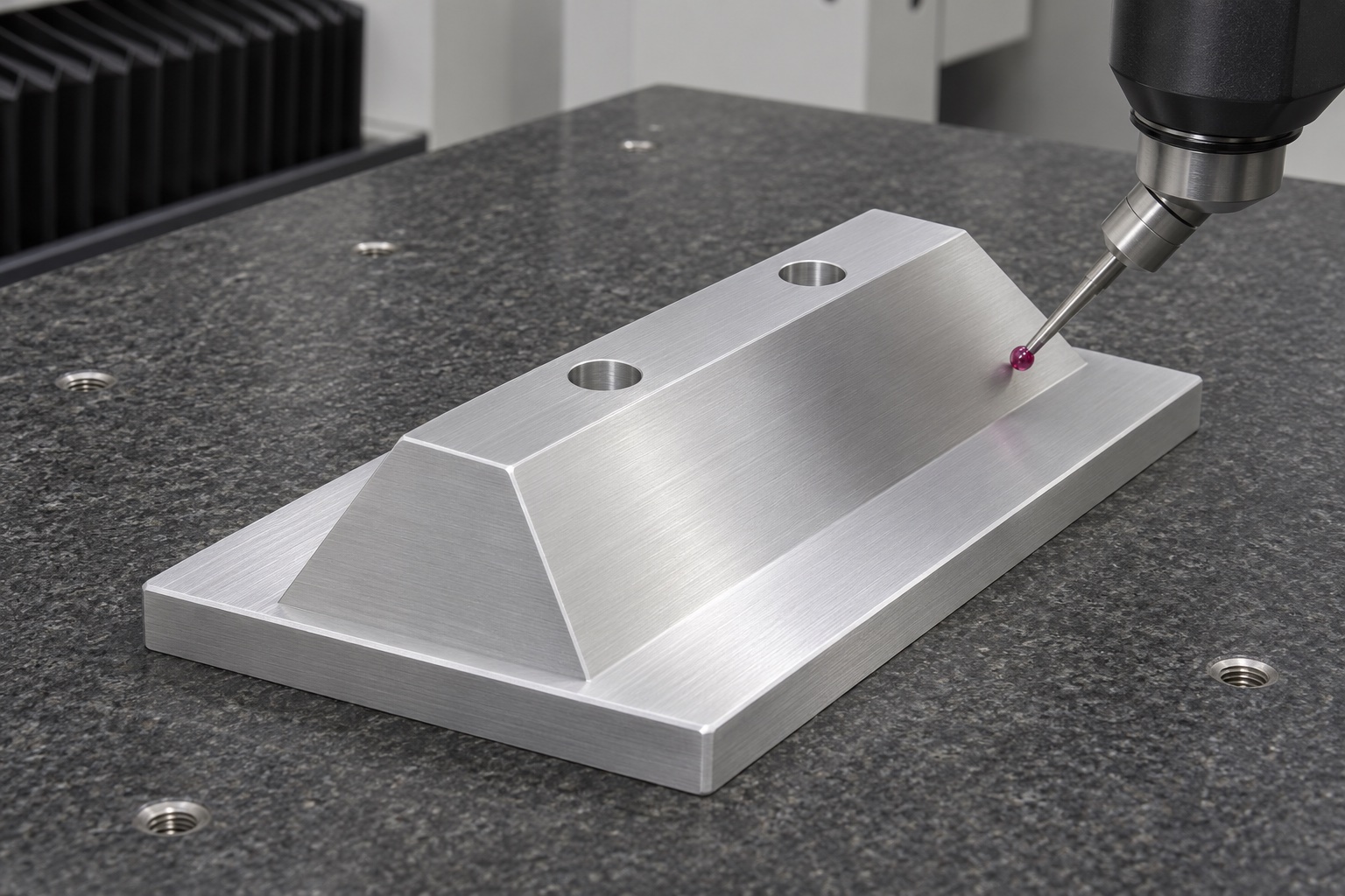
The proposed inspection record would cover the base reference, ridge section, sloping-face relationships and the mounting pattern according to the actual drawing. The method would be chosen for accessible surfaces and required uncertainty. Profile sampling and part support would be recorded so that another reviewer could understand what was measured. A check of only overall length and hole diameter would not address the locating interface. The example does not supply numerical results because no sample has been measured. Any eventual report would identify actual instruments, characteristics, results and acceptance decisions for the real component.
Bound an optional assembly trial
An optional observation could examine orientation, insertion, seating and screw access using identified mating components. It would record the relevant revisions and assembly procedure. A favorable hand-fit result would not demonstrate alignment repeatability, vibration resistance or retention capacity. Unexpected rocking or binding would lead to a review of contacts and geometry before either component was modified. Approved changes would enter revised drawings and inspection instructions. A hand-adjusted demonstration part would remain identified as such and would not automatically authorize shipment of production components or release a medical analyzer for operation.
Package the working surfaces individually
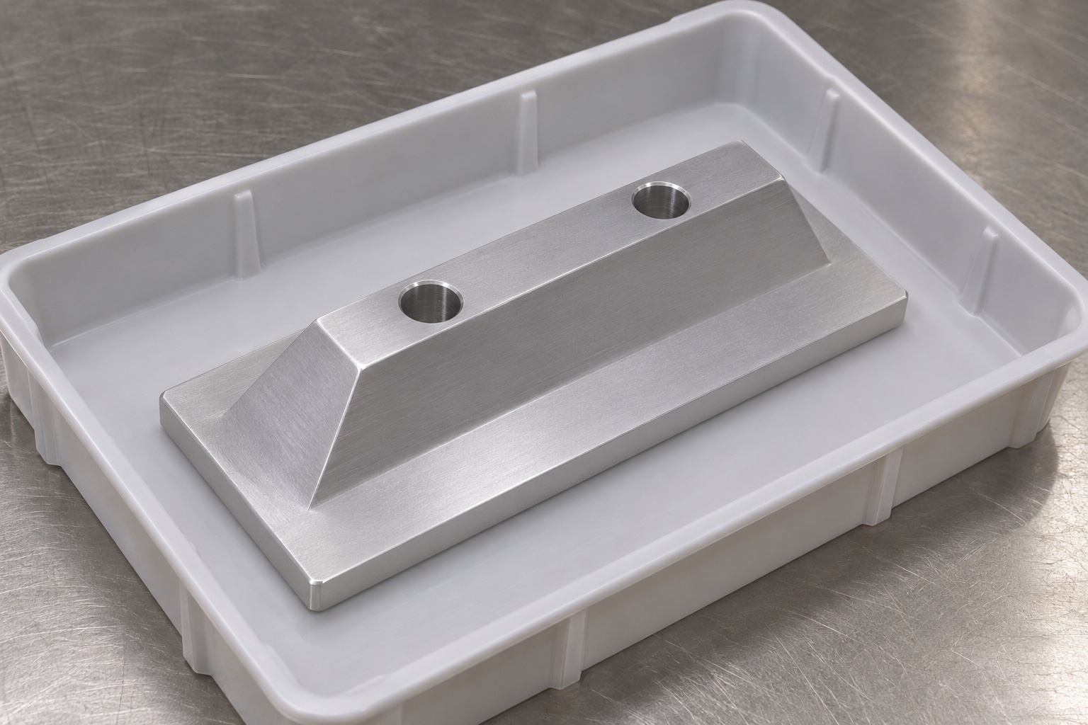
The proposed packaging would prevent the sloping faces and base from contacting neighboring components. Tray contact locations, protective sleeves or other separators would be selected to avoid damaging the approved finish. The package would identify the part number, revision and inspection status. It would not be labeled sterile, and no validated cleanroom delivery condition would be implied. If the purchaser required a particular cleaning or packaging protocol, that scope would need agreement before manufacture. Packaging changes would also be reviewed where an adhesive, foam or film could leave unwanted residue on a functional interface.
Define what a repeat order would preserve
A repeat manufacturing package would retain the rail section, reference system, mounting holes, mating concept, approved process scope and inspection condition. Changes to a module, screw or coating would be evaluated even if the rail silhouette appeared unchanged. The purpose of the example is to make a quotation and review conversation specific enough to support traceable decisions. It does not replace the equipment designer's verification of the complete locating and retention system. No customer identity, delivery history or measured improvement is claimed, and future acceptance would depend on the actual released documents and evidence.
Manufacturer background reference: www.carrlane.com.
FAQ
Does this case describe an actual customer delivery?
No. It is a representative manufacturing example explaining a proposed review and CNC workflow. No customer, production quantity, measured tolerance, delivery date or operating result is presented as a fact. A real project would require its own approved inputs and evidence.
Why is the profile not called a dovetail?
Its raised ridge narrows upward and does not have the retaining undercut of a captured dovetail interface. The illustrated component is an angled locating rail. Its mating and retention arrangement must be defined separately rather than inferred from the product name.
What would control the mounting-hole geometry?
The released drawing would define the holes relative to the functional base and ridge references. The concept has two plain holes only. Screw seats, threads or additional retaining features would require an authorized design change and appropriate inspection requirements.
Are numerical machining tolerances promised?
No. This example contains no measured sample or universal tolerance commitment. A supplier would review the actual dimensions, material condition, finish, inspection method and required uncertainty before agreeing a manufacturable and verifiable acceptance basis.
Would a manual fit test qualify the analyzer mechanism?
No. It could document limited observations such as orientation and access under a recorded procedure. Repeatability, retention, environmental stability and safety-related requirements require evaluation of the complete real assembly by the responsible equipment team.
What belongs in the quotation package?
Include controlled drawing and model files, the mating contact concept, retention arrangement, material condition, final finish, quantity, inspection scope and protective packaging requirements. Identify unresolved interfaces before manufacture rather than relying on a photograph or an unrecorded hand-adjusted sample.

tanghangyun@oemach.com